
Hey thanks for the reply!:) I actually got her to work. I had to trace the circuit and I finally found a break between the C2 cap. It is the 22n. When using axial caps it seems you jump over this connection. If I would have used radial caps I would have been okay. I'm guessing it was something I did as most times! It is plenty loud now! Oh yeah.. With a little help from my good friend from around these parts told me I should change Q2 from a 2N5088 to a different transistor. I opted for a 2N3904. Was I supposed be jumping on this build? It is the Ver.2. Thanks again!
- Welcome to madbeanpedals::forum.
This section allows you to view all posts made by this member. Note that you can only see posts made in areas you currently have access to.
Pages1
#2
Tech Help - Projects Page / Re: Volume drop with Snack Shack….
September 02, 2013, 03:57:36 AM
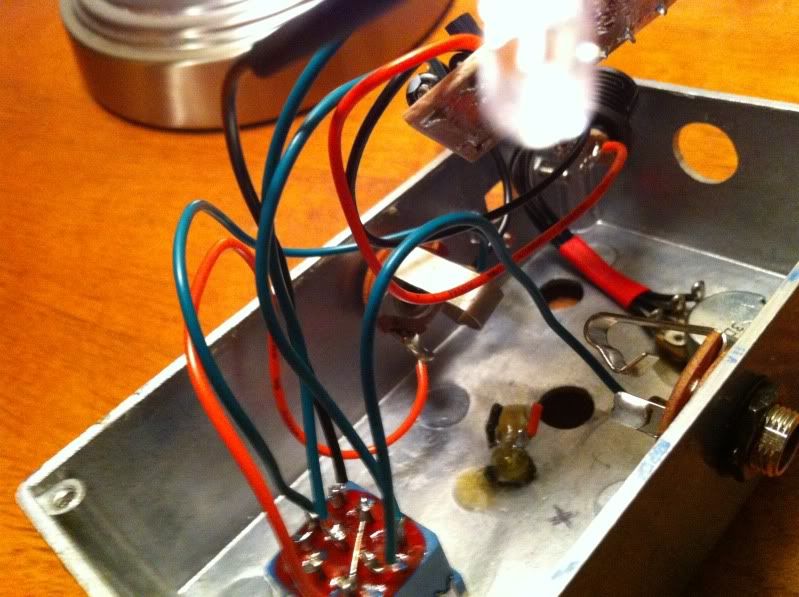
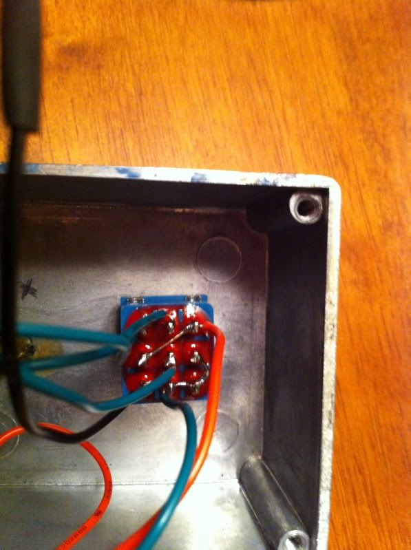
I wanted to add.... The box that it is housed in is my "test box". I thought it might be a jack/grounding issue. the pedal is in the very "draft form" at the moment.  Thanks!
Thanks!
#3
Tech Help - Projects Page / Volume drop with Snack Shack….
September 02, 2013, 03:55:46 AM
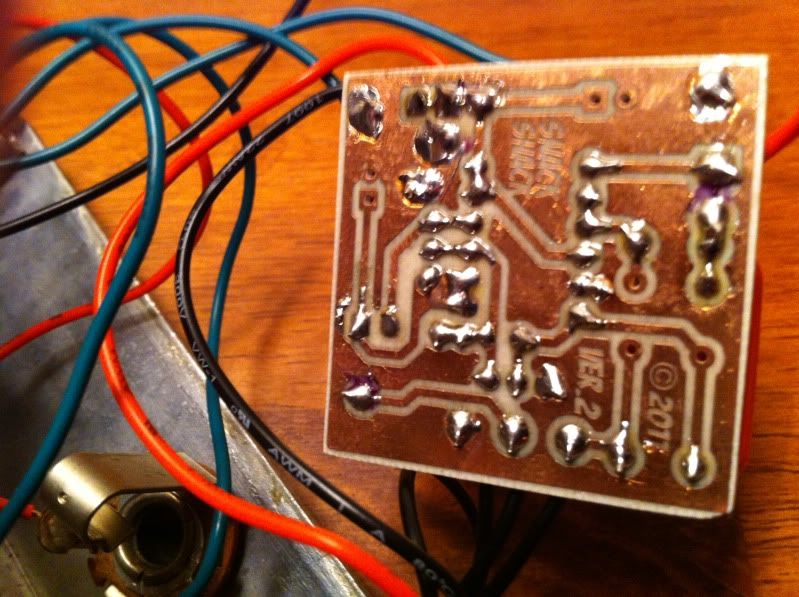
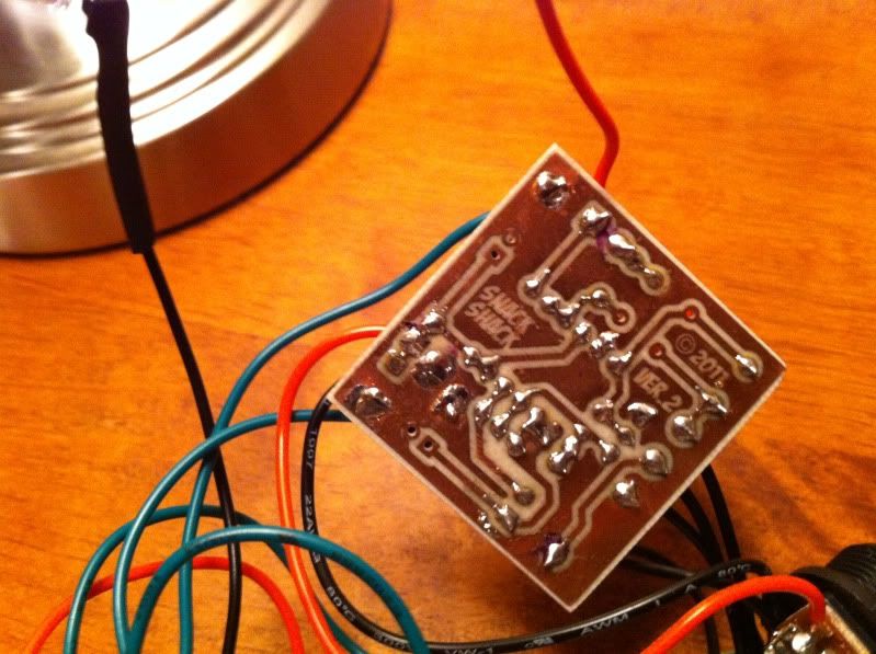
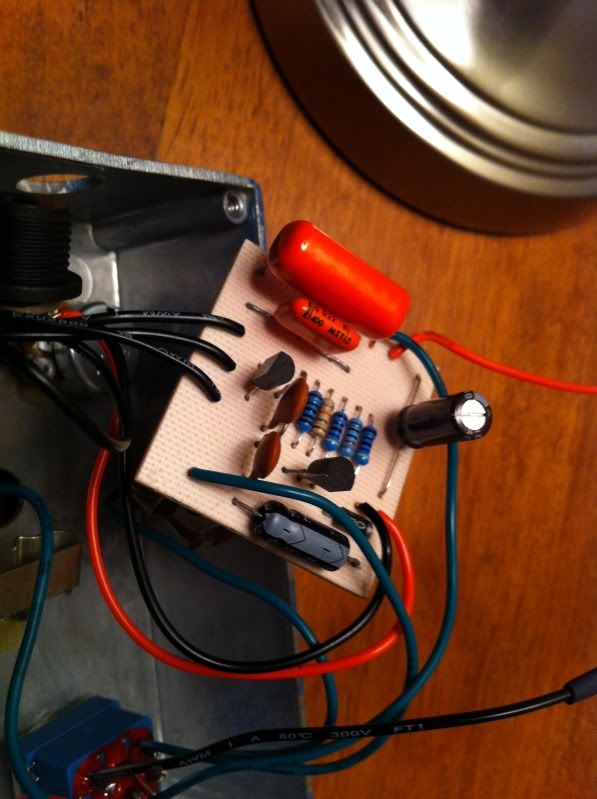
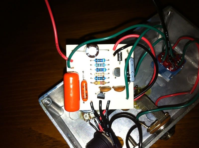
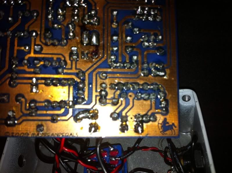
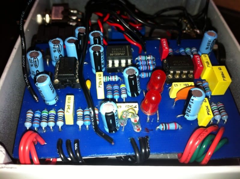
Hello there! Can anyone help with my Snack Shack build? The pedal works engaged and in bypass. But...... When engaged there is a massive volume drop. Am I supposed to jumper somewhere when using axial caps as compared to radial? I'm kind of stumped. I used a 2N5088 in the Q2 spot. Other than that all the values are correct. When I touch the Out point on the back of the PCB with the C4 + the volume is where it is supposed to be. Any ideas? Here are some pics. Thanks so much guys!


#4
General Questions / Re: Kingslayer... No switches... Do I solder a jumper??
April 27, 2013, 01:59:44 PMQuote from: midwayfair on April 27, 2013, 04:32:01 AM
Yes; without the jumpers, the diodes will never be connected to ground. Use your multimeter to check continuity to make sure you jumper the right pads.
Thanks man! So there is no hard and fast rule about what pad to jumper? Thanks again!
#5
General Questions / Kingslayer... No switches... Do I solder a jumper??
April 27, 2013, 02:14:32 AM
Hey guys! I'm opting not to do any switches with my Kingslayer. Do I have to solder a jumper wire in the clip holes on the PCB board or leave them open? Thanks so much guys!!!:)
#6
Tech Help - Projects Page / Re: Old Klon clone layout?? Anyone have the diagram??
April 19, 2013, 05:53:54 PM #7
Tech Help - Projects Page / Re: Old Klon clone layout?? Anyone have the diagram??
April 19, 2013, 03:47:29 PM
Hey:) This is helping me but does anyone know where to find Ver.1??? The very first one. Thanks!
#8
Tech Help - Projects Page / Re: Old Klon clone layout?? Anyone have the diagram??
April 19, 2013, 05:46:10 AM
You sir rock!
#9
Tech Help - Projects Page / Old Klon clone layout?? Anyone have the diagram??
April 19, 2013, 03:13:42 AM
hey got this guy in for repair......
Anyone have to original wiring diagram and layout? That would be GREAT!!! Thanks:)


Anyone have to original wiring diagram and layout? That would be GREAT!!! Thanks:)
#10
Requests / Re: Pic of Ego Driver wiring footswitch to newest board?
April 15, 2013, 10:11:40 PM
Got it! Thanks so much:)
#11
Requests / Re: Pic of Ego Driver wiring footswitch to newest board?
April 13, 2013, 08:48:06 PM
Also... If not using the 2nd clipping mod. Do you leave the holes on the PCB open or do you have to jumper them? Thanks!
#12
Requests / Re: Pic of Ego Driver wiring footswitch to newest board?
April 13, 2013, 08:00:11 PMQuote from: madbean on April 13, 2013, 07:49:12 PM
For footswitch wiring, the standard diagram is what I use: http://www.madbeanpedals.com/tutorials/downloads/StandardWiring_MBP.pdf
Let me know if you need any more help.
Thanks so much for the reply! I will go over this and see where I went wrong. The LED came on but does not go off...
 Thanks again and I will report back one way or the other.
#13
Requests / Pic of Ego Driver wiring footswitch to newest board?
April 13, 2013, 06:36:52 PM
Hello. First Madbean build and things are going smooth. Hey I am on one hangup. I have the newest version of the board and I am a bit confused to some of the lug wiring to the PCB. 1A lug in question and a couple of others. Can someone show a completed pic of their build showing the wiring. Sorry if this has been discussed. I did a quick search and could not find any. A lot of the pics were for the old board. Thanks so much in advance!
First Madbean build and things are going smooth. Hey I am on one hangup. I have the newest version of the board and I am a bit confused to some of the lug wiring to the PCB. 1A lug in question and a couple of others. Can someone show a completed pic of their build showing the wiring. Sorry if this has been discussed. I did a quick search and could not find any. A lot of the pics were for the old board. Thanks so much in advance!Pages1