News:

Forum may be experiencing issues.

Main Menu
Menu

Show posts

This section allows you to view all posts made by this member. Note that you can only see posts made in areas you currently have access to.

Show posts Menu

Messages - decsnspace

#1
Open Discussion / Re: Price of the Pt2399's (fake?)
June 02, 2016, 02:20:32 AM
I know I'm late to this party but I'd definitively be in for 10 Paul. Got a few delay/reverb builds still in my build queue.

Sent from my SM-G530T1 using Tapatalk

#2
Open Discussion / Re: High end helping hands
June 01, 2016, 11:27:39 PM
I bought one of those blue pcb holders on amazon.  I used it maybe once or twice but eventually I reverted back to just using my own 2 hands and some blu-tack. It's a nice tool but IMO it causes as many problems as it solves. Won't be a change your life purchase by any means.

Sent from my SM-G530T1 using Tapatalk

#3
Quote from: rullywowr on October 29, 2013, 06:41:34 PM
Quote from: jimilee on December 11, 2012, 05:31:32 AM
Pedal Vectorpack is what I use.
http://www.ontheroadeffects.com/vectorpack/

Just like jimilee, I like the pedal vector pack myself.  I use Inkscape and import them right into the project.  Double click on the outlines you want (or use shift+ drag selection) and then I copy it into a new layer.  Makes it really easy to visualize how the pedal will look, including knobs and hardware.

I like to put things on different layers, so I can turn them on/off at will.  I usually do layers something like:

(in no particular order)
Enclosure Outline
Knobs/Hardware
Decal/Artwork
Drill points
PCB (if you want you can import that too)
Drillpoints

I get my drill points aligned up using the Allign/Distribute tool (SHIFT + CTRL + A).  After that, it is awesome to just select the point, select a knob from the pedal vector pack and have it aligned right where it should be.  The alignment tool is one of my favorite features about Inkscape.  Makes it super easy to make sure things are in a straight line.  Then you can turn off the "knobs" layer and just print out your decal/waterslide/etch etc....I leave the drill points there so I can also use it as a drilling template.  Whoo hoo!
Haven't tried these out as I'm not as versed using illustrator as I am with photoshop. I did download the pedal vector pack though and really like what I see in the templates with all the "actual size" knobs and hardware options available.
When I get some more time I'll have to delve into illustrator and see if I can come up with something usable for future projects.
#4
Very cool!
Thanks for updating that link juansolo!

I went ahead and saved your new templates just in case I make the same mistake again.
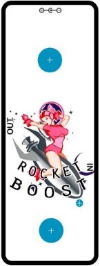
Here's what my Bacon Bits (aka "Rocket Boost") design looks like that I created using your template. I replaced the 9vDC text with the cent_neg.jpg which I found on google.


#5
juansolo,
I downloaded the pstemplates that you posted a while back. The templates have been very helpful for me to use as a base template design for creating guitar pedal images in photoshop. However I recently copied over the file I had for your 1590A enclosure and now the link to your website seems to be broken or dead.
Did you happen to move the templates to a new location on your site or did you just decide to take them down?
Any chance you might be able to provide a new link for us or maybe post a copy of your 1590A template that I could use?
If so, much appreciated as I'm currently building the bacon bits, runt, and afterlife and this template would be a lifesaver! Thanks! ;)
#6
Quote from: muddyfox on October 21, 2013, 04:31:26 PM

I have this tiny contraption permanently plugged in my breadboard which contains two led positions and two B100k pots (what I had no use for at the time).
I use it not only to find the appropriate CLR value for any particular led (as the chinese bulk ones vary wildly in brightness), I also use it for brightness matching when the pedal calls for two (or more, or different color) leds. Comes in quite handy and doesn't take much space.

That is another great idea. I didn't realize these LEDs varied so much.
I just tested one of the ultra blues using Mike's suggestion with a 50k pot, and the value I came up with that didn't burn the back of my retina was @ 33k. Your idea takes it a step further for matching LED intensities.
Awesome, thanks to all again! Great info!
#7
Quote from: Thomas_H on October 21, 2013, 04:04:51 PM
Something between 10k and 33k should work. try 22k and hold it to a 9V battery to try it out.
Thanks Thomas, I have resistor values on had in that range I will give them a try.

Quote from: Mike B. on October 21, 2013, 04:13:07 PM
What Thomas said. Or, if you want a specific brightness, just use lugs 1 & 2 of a 50K pot and 9v battery and adjust to taste. Then measure the resistance you ended up with and match it with a fixed resistor. Just be careful not to start with the pot set too low.
Great additional info Mike! I think I may have a 50k pot around here somewhere, that should give me a good idea of what value I'll need so I don't go blind here!

Thanks to both you guys for the assistance. My soldering experience is top notch, but sadly my overall electronics knowledge is a bit lacking... Everyday I'm learning something new and today is no exception, thanks again! ;)
#8
Just finished building a bacon bits booster pedal. I usually use green LEDs with my pedal builds but I only had some Ultra bright blues on hand that I picked up on the cheap from Tayda. I was contemplating just ordering some new greens and replacing it, but I seem to recall reading somewhere that increasing the value of the LED resistor can dim the brightness. I'm currently using the standard 4.7k that madbeans suggests, anyone had any luck with dimming these ultra bright blue LEDs and if so what higher resistor value works well in accomplishing this?

Here's the specs of the ultra blues from Tayda:
Emitting color: Blue
Diameter: 3mm
Lens color: Water clear
Usage voltage(V): 3.2-3.4
Current(MA): 20
View angle: 20 - 25
Luminous intensity(MCD): 18,000


#9
After a lot of scratching  my head and troubleshooting I finally found the issue. It was a bad solder joint on the ground connection between the input jack and the 3dpt switch. Must have completely overlooked that connection when doing continuity checks. I re-flowed the solder joint and now the LED works perfect!  :D
#10
Thanks for the replies. I was just testing it out again with the back open and LED lit up on a few occasions when I pressed the switch and then sometimes would either flicker or not light up at all. I'm guessing there must be a short somewhere or a cold solder joint. Looks like I'll need to do some more investigating and maybe re-flow some of the solder joints that connect the LED ::)
#11
I've just finished building a green russian mudbunny.
The pedal works great and sounds really good, but the LED doesn't come on when the pedal is on.

The mudbunny build pdf doesn't show the chasis wiring, so I just followed the standard madbean pedal wiring on the project home page: http://www.madbeanpedals.com/tutorials/downloads/StandardWiring_MBP.pdf

I've wired the pedal using the 4.7k resistor shown and I am also using a 3mm Green LED.

Based on the wiring diagram I used any ideas of what I may need to do to get the LED to turn on?