News:

Forum may be experiencing issues.

Main Menu
Menu

Show posts

This section allows you to view all posts made by this member. Note that you can only see posts made in areas you currently have access to.

Show posts Menu

Messages - MAXstruments

#1
Hallo,
I tried everything getting this project to work. Many hours with no luck.
But I'm out of ideas and knowledge how to proceed. :-)
I checked the wiring, components, soldering and everything for several times. But I've found no mistakes.

I have not connected the mod toggle jet and have no clamp mod done.

Problem:
I have a clean and dry signal through the effect.
If I turn all the poti's to maximum i can hear one repeat.
But it is not very loud.  I measured the regulator and it outputs 4,9v.

IC Voltages:


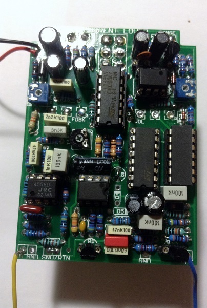
IC1 (TL072)
1 - 4,8v
2 - 4,8v
3 - 4,8v
4 - 3,1mV
5 - 4,4v
6 - 4,8v
7 - 4,8v
8 - 9,6V
                                 

IC2 (PT2399)
1 - 4,9v
2 - 2,4v
3 - 3,4mv
4 - 3,5mV
5 - 2,7v
6 - 4,4v
7 - 11mV kind of moving
8 - 0,5V
9-16 - 2,5V
                                 

IC3 (TL062)
1 - 3-6v moving
2 - 4,7v
3 - 4-5v moving
4 - 60mV
5 - 4,7v
6 - 4,7v
7 - 4-5v moving
8 - 9,5V


#2
Thank you for the help.
#3
Thank You,
i did what you suggested and was able to get it biased. The Sweet spot is around 34 KHz.
I have now flanging without distortion. Unity gain volume in 9v operation is still at 3 o clock. Is that normal?

I also have a other question. Measuring resistance in  a circuit does not always gives clear results. Right?
In circuit R35 for example reads as 100k. Why is that? Other resistors return only moving results. Is that a DMM issue?
#4
I have but never used it. Here the measurements against G.

Matrix Mode (switch down)
CCW : pin2 = 301,6 kHz, pin6 = 301,6 kHz
CW: pin2 = 13,3kHz, pin6 = 13,3kHz
(switch up)
CCW : pin2 = 70 - 300 kHz moving, pin6 = 70 - 300 kHz moving
CW: pin2 = 17-200 kHz moving , pin6 = 17-200 kHz moving (sometimes it looks like it's jumping from 200kHz to 800kHz for a moment)
#5
i put the trimmers in their middle position.
Matrix Mode (switch down)
CCW : pin2 = 4,6v, pin6 = 4,6
CW: pin2 = 4,7v, pin6 = 4,6
(switch up)
CCW : pin2 = 4,7v, pin6 = 4,7
CW: pin2 = 4,6v, pin6 = 4,3
#6
Hey,
Thank you for the reply.
I put sockets in for R12 and tried 47k and 22k. It changes only the range of the bias but not the distorted flanging like sound.
#7
Project: Current Lover

Hallo,
I have an non working current lover on the table. He is really giving me a headache.
I spend more then four times the build time debugging this thing. Sadly with no success.
I read all the post on this forum regarding current lover debugging. My problem is nearly like this one:

http://www.madbeanpedals.com/forum/index.php?topic=4009.msg35687#msg35687

But there was no solution to this problem in the above thread.
I'm not ready to give up jet. Maybe someone has an idea!

Thank you for any Help
Max

Changed Values: I have a B1M rate poti mounted and a 1n914 for D2.

Problem:
Ich get only a a wet signal if the bias and clock trimmers are fully open. But its not a real flanging effect.
It also is a little distorted. All potis have some functionality.
I have to turn the volume 3/4 up to get unity gain compared to the bypassed signal. He is not boxed.

What have I Done:
I mesured all resistors. I checked all caps for their markings and verified them. I checked many times for bad soldering or bridges.
I tried to bias with 12v but R33 startet smoking. I tried different values for C18. 10pf, 15pf, 22pf, 220pf.
I noticed that pin7 and pin8 of MN3007 have only output if the bias trimmer is almost fully open.

IC Volteges (9.6v) with switch in flange mode.


IC1 (JRC4558)
1 - 4,8v
2 - 4,8v
3 - 4,2v
4 - 0,4mV
5 - 4,8v
6 - 4,7v
7 - 4,7v
8 - 9,5V


IC2 (MN3007)
1 - 9,5v
2 - 4,7v
3 - 2,4V
4 - 0,8mV
5 - 3,3mV
6 - 4,7V
7 - 3,3V
8 - 3,4V


IC3 (CD4049)
1 - 9,5V
2-7 - 4,7V
8 - 1mV
9-12 - 4,7V
13 - 0,3mV
14/15 - 4,7V
16 - 30mV


IC4 (CD4013)
1/2 - 4,7V
3 - 7-8V varies
4 - 0,4mV
5 - 4,7V
6-12 - 0,4mV
13 - 9,5V
14 - 9,5V


IC5 (LM324N)
1-3 - 4,7V
4 - 9,5V
5 - 1-2V varies
6 - 1-2V varies
7 - 1-3V varies
8 - jumps from approx. 1V to 8V
9/10 - 4,4V
11 - 0,4mV
12/13 - 4,3V
14 - 4-5V moving


IC6 (LM311)
1 - 0,5mV
2-3 - 1-4V varies
4 - 0,6mV
5/6 - 9,58V
7 - 7-9V varies
8 - 9,58V