News:

Forum may be experiencing issues.

Main Menu
Menu

Show posts

This section allows you to view all posts made by this member. Note that you can only see posts made in areas you currently have access to.

Show posts Menu

Messages - kryoz

#1
Tech Help - Projects Page / Re: Chunk chunk question
March 31, 2013, 05:35:24 AM
1.- You could just use any combination that reaches 30n, like 22n and 8.2n, or 18n and 12n, 3.3n and 27n, or just use a 33n and leave the other empty.

2.- the bias @ 4.5v is a starting point, it depends on your transistors, and other component values, as well as your power supply, if you are @ 9VDC you could start with 4.5v on all trimmers and then moving it up a little, maybe the first stage with a couple more mV, and the rest at 4.5v.

On mine (running it @ 12vDC) i have the first two stages a little higher than the other two.

Use your ears to taste.

Hernan.
#2
The trim is just to get the same volume with the effect on or bypass, so it´s pretty easy, move the trim until you get the same amount of volume on both status.

Hernan.
#3
aballen is right, from the image posted i think you are using this file

"tonepad_rossphaserOLD.pdf 154.7 KB-- Ross Phaser OLD, Rev.4.Nov.29.2005"

and should be using the layout on this file

tonepad_rossphaser.pdf 255.1 KB-- Ross Phaser, Rev.1.Nov.29.2005

If you take a look at the tonepad´s .pdf file, you have U,V,W,X,Y,Z pads in a row between the two bottom ics.

If you already etched the previous layout, you´ll have to cut some traces, use the schematic as a guideline in order to hook up the extra stage.

Hernan.
#4
Hey guys, thanks for your feedback.

I am begining to think the same, it´s the op amp, i can´t understand why, but until i don´t test the circuit with a TL062 i can´t  think of anything else.

I`ll have to wait until Wednesday to get a TL062 due to easter holidays in Argentina, then i´ll post my results.

Hernan.
#5
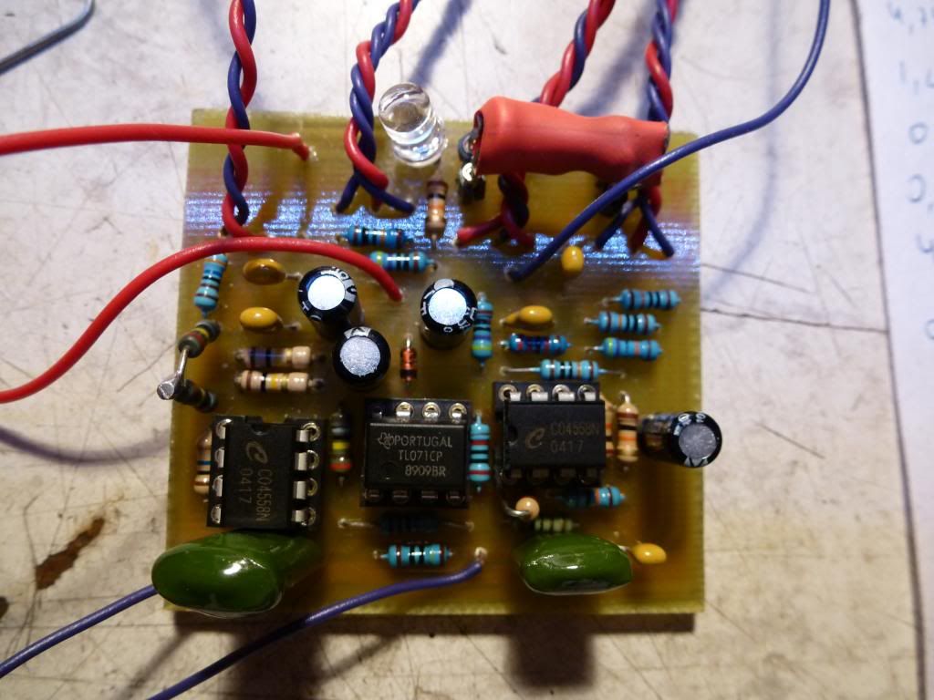
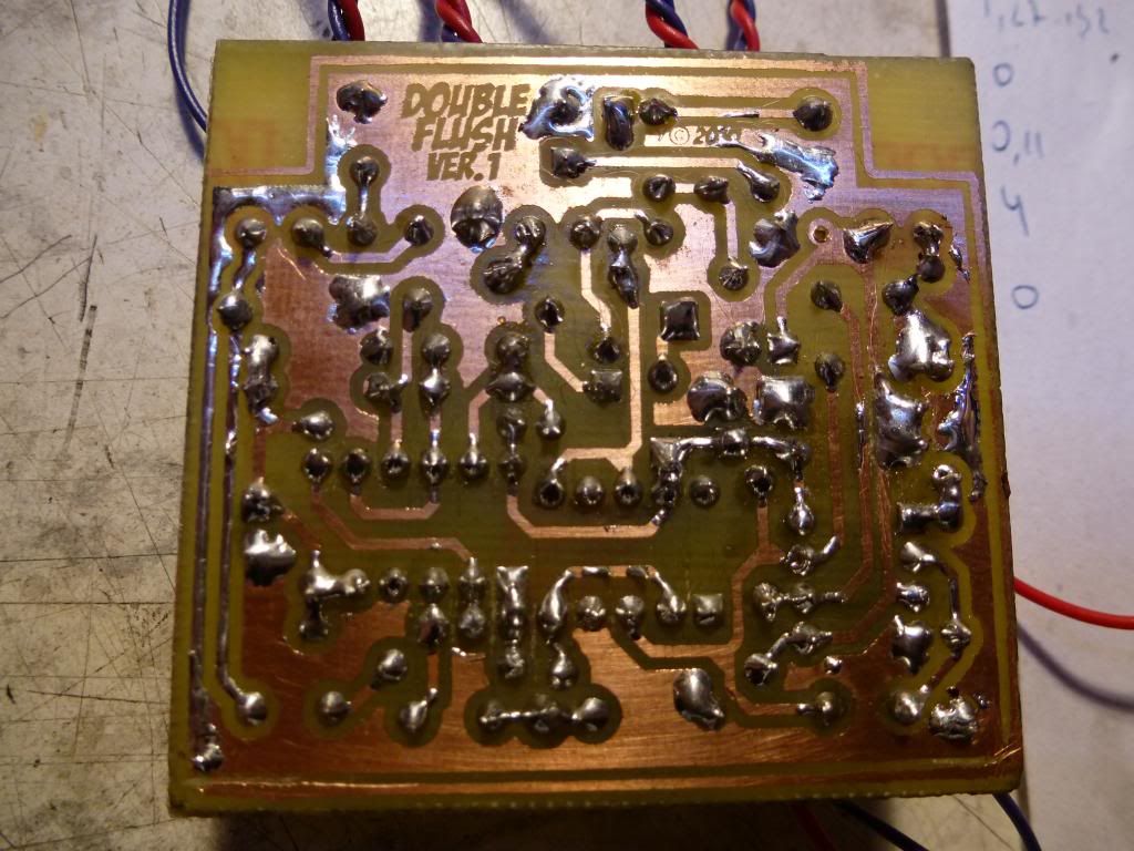
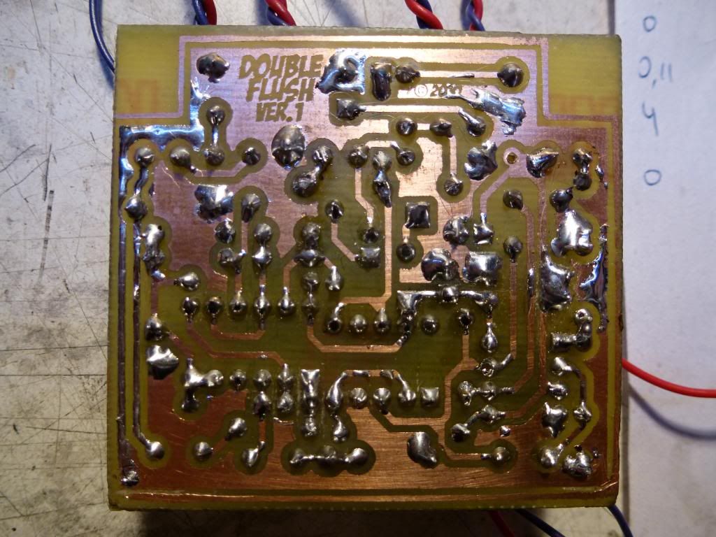
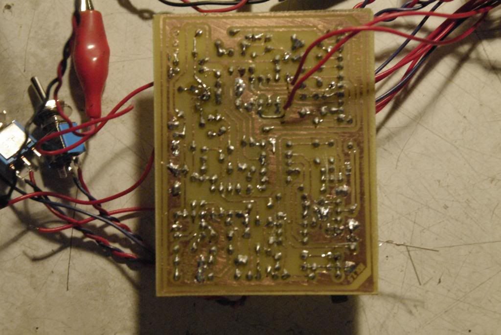
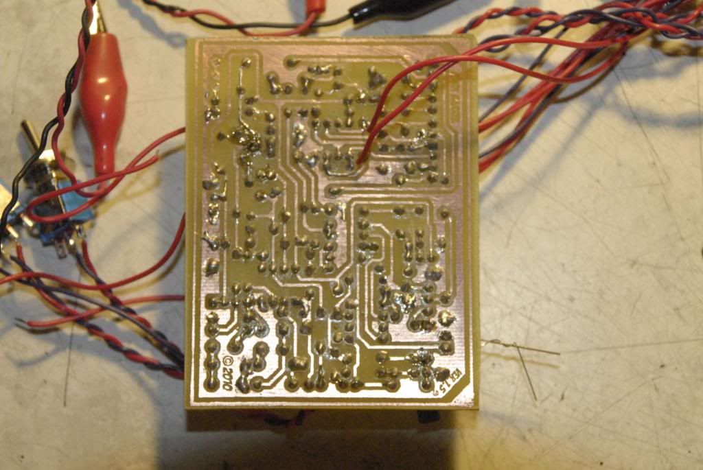
Little update, i`ve triple checked and measured component values and tested tracks for solder bridges/cold joints, reflowed all the oscillator components, and took pictures.


#6
Tech Help - Projects Page / Re: 2n5087 substitution
March 28, 2013, 11:21:57 PM
BC560 should work also (look at the pinout).

Hernan.
#7
Tech Help - Projects Page / Double Flush No Tremolo
March 28, 2013, 11:11:45 PM
Hello everybody...

I´m trying to debug my Double Flush build (current revision, etched) found in this link.

http://www.madbeanpedals.com/projects/DoubleFlush/docs/DoubleFlush.pdf


I have made the following substitutions because i could not source the original components.

IC3 - TL082/NE5532/LM1458/JRC4558 (TL062 listed).
IC2 - TL071 (LF351 listed).
R14 - 20k (18k listed).
R16 - 1M8 (2M2 listed).
R18 - 3M6 (3M3 listed).
LDR2 -Roll-your-Own Red diffused 5mm led and LDR (VTL5C1 listed).


The problem that i have is that the oscillator around IC3 doesn´t work, both status and LDR leds stays fixed.

I have audioprobed the circuit and the clean signal goes from the begining (R1-C1) to the end (R11) without problems.. but i get a clean signal only, The BAL, VOL and INT pots seem to work, because INT pot dimms both leds, VOL reacts normal and BAL goes from clean signal (JRC4558 side) to very weak signal (LF351 side).

I have also double checked component values, orientation and solder bridges/cold joints, etc.

Things that i have thinked going trough with the scheme.

- I measured 5.29 v between R22-R23, shouldn`t this be 1/2 VC? i´ve replaced both 100k resistors with new ones.
- I have 4.55v between R20-R21.
- The pulse pot doesn´t work (obviously).
- Pin 3 @ IC2 when measured turns off the leds and i have to reset PSU.
- I have soldered a 100k trimpot as a variable resistor between VC and GND and when turned manually, leds dimm and blink up again.

My DMM readings @ 9.02 VDC

IC1 (JRC4558)

1.- 4.30.
2.- 4.26.
3.- 3.81 (Voltage Drops to 3.38 when measured).
4.- 0.
5.- 3.78 (Voltage Drops to 3.40 when measured).
6.- 4.25.
7.- 4.32.
8.- 8.28.

IC2 (TL071)

1.- 0.11.
2.- 4.74.
3.- 1.32 (Voltage Drops to 1.27 when measured).
4.- 0.
5.- 0.11.
6.- 3.96.
7.- 8.31.
8.- 0.

IC3 (TL082)

1.- 3.70.
2.- 3.88.
3.- 4.01.
4.- 0.
5.- 4.00.
6.- 4.01.
7.- 3.95
8.- 8.29.

I will try to get a couple of TL062 next week because i am begining to think that this IC is vital for the circuit.

I will upload high res pics as soon as i can.

Thanks in advance for any tip you have if you see something that i missed.

Best regards.

Hernan.
#8
Well, just to finish this thread, long story short... tried external oscillator, chorus came to life... lifted all parts from the LFO section, replaced with new caps and new resistors, throwed in the tl082, hooked it up... voila! flawless chorus...

Thanks you all for your feedback

Hernan.
#9
Hi, thanks for your feedback...

Yes tl022/062/l072/082 should be interchangable they just have different specs according to power draw and noise.. but basically any dual op amp with the same pinout should fit this circuit... most common opamps used in stompboxes are these and lm1458/ne5532/jrc4558/lf353 etc etc.

i have even tried a non-fet IC like LM2904 (which worked like a charm on my phase90 to eliminate LFO noise) with still no luck..

I am building an external oscillator to test the rest of the circuit and then i think i´ll replace all parts on the LFO section one at a time to check faulty components.

I guess that problems like these are where the fun in DIY is at.

Hernan.
#10
Yes... it looks scratchy because when i was searching for soldering hairs in between traces i cleaned it with isopropyl alcohol and brushed it with a copper brush..

i have already tested for continuity in the traces and audioprobed the circuit... but guess i am doing it again...

thanks for your reply.

Hernan.

BTW. forgot to say that R34 is lifted above IC2 because i was tweaking it with an external 50k pot, that´s why there is also 2 red cables soldered to R34 pads.
#11
Here are my pics... soldeing job look kind of ugly after redoing some pads...


Hope it helps.

Hernan.
#12
Hi Jacob, thanks for your reply.

I´m using PorkBarrel_ver.2.pdf from the documents in this .zip

http://www.madbeanpedals.com/projects/PorkBarrel/docs/PorkBarrel.zip

You´re right, i will post HQ pics later.

Hernan
#13
Hi everybody... my name is Hernan and i am from Argentina..

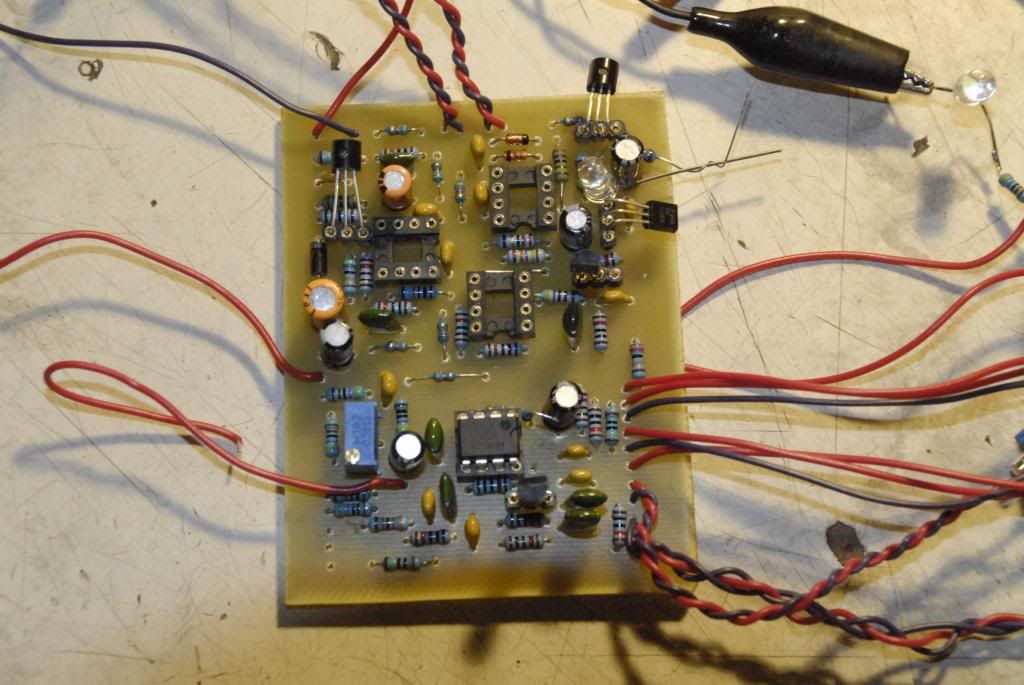
I am really sorry that my first post here is about asking for help but i really have no clue of what is going on with my pork barrel build.. I´ve been reading FSB and DIYSB and building a couple of projects for the last years.

I´ve etched a previous version of the pork barrel (the one with all the tonepad´s mods) and have been debugging it for 3 days...

The problem is that my build is not chorusing at all, i have signal but only a kind of "clean enhanced" signal.

The only two substitutions that i made to the original project is IC2 (tried TL082, NE5532, LM1458 and lastly the non-FET LM2904 just to check) and replaced R40 from 33 ohm to 47 ohm.
The Mix pot is working as far as i can tell, it goes from clean signal to "clean enhanced" but the depth and rate pots don´t do anything.

I have double checked all the parts orientarion, values, checked for solder joints or traces cut.
I have audioprobed the circuit from the begining to the end.
I have tweaked the 10kb trimpot and goes from distortion to clean signal, but no chorus.
I have also tried 6 different MN3007 from two different suppliers, and 2 different MN3101.
I have signal on pins 7 & 8 of the IC4 (MN3007) so i think IC is OK.
I have tried debugging the circuit @9v, 10v and 12v DC.

I think the problem is the LFO around IC2 i can´t get it to work.. i´ve tried stock version and trying to find the problem i did the Depth Mod replacing R39 (4k7) for the 22k + LED to see if the led blinked. Led stays on (dimmed but on) at all times, does not change with the depth pot, it stays fixed... i have also tweaked the feedback resistor (R34) between the 2 Opamps on IC2 with no success.

I am taking a breath from this circuit and tomorrow i will try a CMOS oscillator to R37 to see if the rest of the circuit is working... But if someone can guide me with any kind of ideas about this problem will definitely help.

My DMM readings  @ 9.03v DC are the following.

IC1 (JRC4558)
1 - 3.69
2 - 3.68
3 - 3.67
4 - 0
5 - 3.68
6 - 3.68
7 - 3.69
8 - 9.02

IC2 (TL082)
1 - 8.44
2 - 4.90
3 - 5.38
4 - 0
5 - 4.90
6 - 4.90
7 - 4.90
8 - 9.03

IC3 (MN3101)
1 - 8.96
2 - 4.51
3 - 0
4 - 4.53
5 - 0.35
6 - 7.60
7 - 3.16
8 - 0.60

IC4 (MN3007)
1 - 8.96
2 - 4.59
3 - 2.99
4 - 0.60
5 - 0
6 - 4.54
7 - 3.51
8 - 3.51

Well that´s it... Thanks in advance.