News:

Forum may be experiencing issues.

Main Menu
Menu

Show posts

This section allows you to view all posts made by this member. Note that you can only see posts made in areas you currently have access to.

Show posts Menu

Messages - Rich_S

#1
Build Reports / Re: Your Grandma's Lorus
May 26, 2014, 08:03:54 PM
Here's the inspiration, my old friend Tina playing her MIJ Paisley at our Drexel U. 25th Reunion in 2009.  The Paisley's always been a band joke with us, because the MIJ RIs first came out around 1985 when Tina was graduating and looking for a new guitar.  The guys in the band were teasing when we said, "You should get a pink paisley guitar 'cuz you're a girl."  Tina, who is in fact quite hippy-ish, was not offended but instead turned it around on us and thought the idea of a pink Paisley Telecaster was awesome.  This is her second, the first being lost in a house fire many years ago.


I'm the fat guy with the red Nashville.  I think if we ever do another reunion gig, I'm going to build Tina a combination dirt box and chorus in a large paisley box.
#2
Build Reports / Re: Your Grandma's Lorus
May 26, 2014, 12:07:26 PM
The guts are a mess.  Since it's a parts-box build, the pots are whatever I had, don't match, and have flying leads.  A Rat's nest, as it were.
#3
I have a Catalinbread Dirty Little Secret that I want to try at 18 volts.  I'm told they sound great that way.  Rather than tie up two outputs from my PP2+, I was thinking of building a Road Rage to stick between a normal 9-volt supply and the DLS. 

I see the 15-volt output from the Road Rage uses its own regulator.  However, I want to run it at 18 volts, without the extra regulator.  Is the 18-volt output from the charge pump sufficiently regulated that it will power a dirt box cleanly?
#4
Build Reports / Your Grandma's Lorus
May 26, 2014, 02:57:58 AM
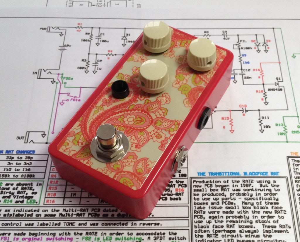
Here's my latest, a Slow Lorus build with only diode clipping.  Low-budget build using mostly parts I had in stock.  I did have to order an enclosure for it, but the first one that arrived had its powdercoating messed up - the coat was thin on the top and showing gray spots through the pink.  I was too impatient to wait for the second box Smallbear sent me, so I started thinking of ways to cover up the gray spots.  Then I remembered I had some samples of stick-on paisley that a guy from the TDPRI sent me a few years ago.  The enclosure was a perfect color match, and I had some tan knobs that matched the decal's background.

The sound is, of course, typically Rat-nasty.


Now I have the replacement enclosure and plenty more stick-on Paisley.  Hmm....
#5
This is really more of a question for freestompoxes.org, but I've been through their old BB Preamp thread several times, and it's a big long mess, full of contradictions and busted image links.  I'm hoping I can get a straight answer here, rather than scraping the goop off for a look-see.

What I want to know is, what clipping diodes are used in the original BB Preamp?  Is it just a single 1N4148 in each direction, or does it use two 1N4148 in each direction?

I'm considering modding a BB with an SD-1 style asymmetrical clipping section, but want to know what's actually in there first.

Thanks all.
#6
I was just ordering some 1N34A diodes off eBay for a Cupcake I'm building.  While I was ordering , I grabbed some 1N270's as well, since I have Distortion+ on the brain.  The D+ schematic I have mentions subbing different diodes for different sounds, it says 1N270 was the original, and recommends 1N34A for a fuzzier sound.

That got me looking at spec sheets, but I don't see specs that would explaing the difference on the sheets.  Namely, both diodes are spec'd with Vf = 1.0.  The 1N34A refers to this as "Maximum Instantaneous Forward Voltage", the 1N270 just calls it "Forward Voltage Drop".

So, noob questions time: how do you know from the data sheets how the diodes are different in a guitar FX clipping application?  Or is it all just experience and folklore, and I just need to ask non-noobs about stuff like this?

Also, since I'm a bit suspect of eBay sellers of nearly obsolete diodes, is there a way I can test them to 1) confirm they are the right part, and 2) tell them one from the other?
#7
I'm obsessed with James Honeyman-Scott's tone on the first two Pretenders albums.  He said in a Guitar Player interview long ago that he used a Boss overdrive, and based on the article's date (and Boss production dates) that points to an OD-1.  No idea which version.

Anyway, I'm not monetarily equipped to buy an original, and building is more fun anyway, so I got the idea to build a dual-opamp OD-1 on a Green Bean board. After reviewing the schematics carefully, I came up with this BOM:


Anybody care to check it for me?

For the time being, I'm planning on building the pedal with the Green Bean's true-bypass scheme.  However, I'm also going to think about a way to keep the buffers active in bypass.  This would require hacking the board to bypass just the guts of the circuit, jumping from Q1's emitter to the input side of C9.

For those with OD-1 experience (originals or clones) what are your thoughts on how the OD-1 compares to modern SD-1s and the whole universe of TS-ish pedals?
#8
General Questions / Re: Cupcake 1.5 .pdf?
December 03, 2012, 02:28:49 AM
Cool beans.  Got it. Thanks.
#9
General Questions / Cupcake 1.5 .pdf?
December 02, 2012, 05:52:11 PM
I've had a Cupcake board in my parts drawer for a long time, and now I want to build it up.  However, I don't have the .pdf instructions for the Ver. 1.5 Cupcake.  I tried following the link in the current .pdf to previous versions, but can't get to the linked file.

Where can I get this .pdf?
#10
I just went to look a Z-Vex' custom shop page, and noticed his banner logo is a lineup of many different-colored Testor's bottles.  The kids wouldn't be unsupervised, and mostly middle- and high-school aged.  I spent a lot of time with Testor's paints in my youth, and I came out okay (give or take).
#11
A couple years ago, I built an Eternity Clone and donated it for a charity auction for the little (24 kids) private school my daughters attend.  I was thinking about doing it again this year but want to give the pedal(s) a bit more of the school's personality.

The idea I have is to turn a few enclosures over to the school, and have the kids paint them.  I'd start with solid-color powdercoated boxes from Small bEar, most likely.  Maybe show them some pix of the handpainted Z-Vex pedals as an example.

Anyway, what sort of paint should I provide them?  I'd want to give them a variety of colors in small quantities.  Whatever it is, I'll want a compatible clear coat to protest the kids' artwork for posterity.

#12
Fixed!  I just reflowed the high side of R17 and added a bit more solder, and it's the nasty, nasty Muff it should be.

The Fuzz Sisters Live!

(Triangle Mudbunny  and vero Fuzzrite)
#13
Before we get to the photos, here are the voltages on the transistors.  (Voodoo PP2+ power supply, Fluke 87 Multimeter)

+ Power terminal:  9.3

Q1
E: 0.172  
B: 0.730
C: 4.38

Q2
E: 0.099  
B: 0.692
C: 1.157

Q3
E: 0.000  
B: 0.003
C: 0.001

Q4
E: 1.199
B: 1.763
C: 3.813

Clearly the problem is in or around Q3.

Edit: I think I found it.  If I measure the high side of R17 on the resistor lead, I get zero.  If I measure on the pad, I get 9.14 volts.  If I push hard on the lead with the probe, it goes up to 9.14.  Cold solder joint on R17. Looking at it with the magnifier, it looks alright on the trace side, but on the component side, I can see a little dingberry of solder, floating in the middle of the hole.  I'll be back after a few minutes to warm up the ol' Weller...

#14
I'm confused.  If one or more transistors were in backwards, wouldn't it just not work at all?

Also, the Mudbunny project instructions call out the 2N5088 as the "normal" transistor, then goes on to say that we can use other transistors, but must be careful to get them oriented correctly.  I assume this means the board is silkscreened for 2N5088s, but don't know if this is a safe assumptoin or not.

Here's the pinout for the 2N5088 that I have, from a Fairchild data sheet.  No idea what manufcaturer made the trannies I have; I bought them from Smallbear.


I guess I'll check this pinout against the PC board layout and schematic tonight.  Four transistors is too many to just start swapping.


Edit, 102 minutes later:  Okay, I checked all four trannies, starting with the Fairchild pinout, and comparing the built-up board to the project layout to the schematic.  As near as I can tell, the layout & silkscreening are correct, and the transistors are all inserted right-way-'round.
#15
Yes on the 2N5088s.  I have some spares, maybe try swapping them after I get the voltage measurements.

Also, in the spirit of "can't leave well enough alone" I spent some more time staring at the solder side with my little Rat Shack magnifier. I might have found a bridge across D3 and D4.  I scraped whatever was there away, but don't really think that was the problem.  Won't know until tomorrow if it made a difference.  I'm goin' to bed.