News:

Forum may be experiencing issues.

Main Menu
Menu

Show posts

This section allows you to view all posts made by this member. Note that you can only see posts made in areas you currently have access to.

Show posts Menu

Messages - NightOwl

#1
Build Reports / Re: Elephant BoogeymEn!
June 06, 2012, 01:10:20 AM
Quote from: jase on June 05, 2012, 09:59:19 PM
I know this will sound stupid but,... I'm not sure what the three grids at the bottom represent.
I know one is the footswitch but what are the other two? Please excuse the noob!

Unless I am mistaken, all three of those bottom grids are footswitches.  njkke's Boogeyman has three, from left to right on the diagram: 3PDT switch for Gain 1, 3PDT switch for Gain 2, and a DPDT switch for the Boost.

I hope that helps.  :)
#2
Quote from: Bret608 on May 24, 2012, 02:14:18 PM
I really like that PPP color on the Fat Pants. Which of their colors is that?
Thanks, I painted the EP+ myself, I just coated it black and sprayed bursts of silver from a distance over it.

If you mean the Fuzz though, it's one of their standard colors called "Candy Teal".
#3
Thanks guys!  The Fatpants is the newest version of the board, I found that it just fits in there.  Gut shots as requested, I could definitely stand to have neater wiring   :) :


#4
I've just finished boxing the last of my first three pedals, thanks to a lot of help from mgwhit  ;D  
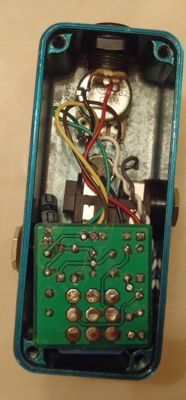
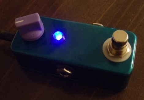
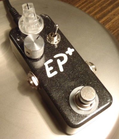
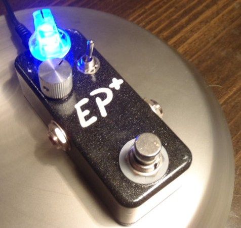
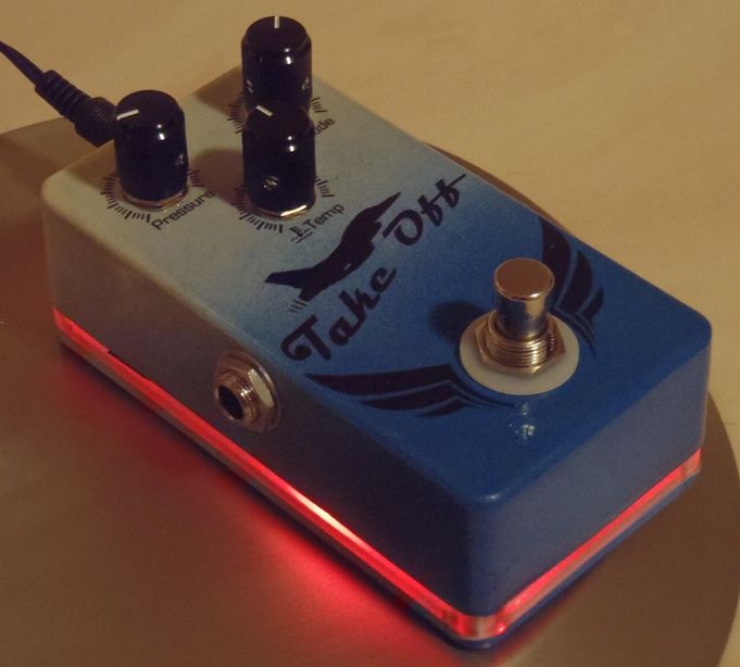
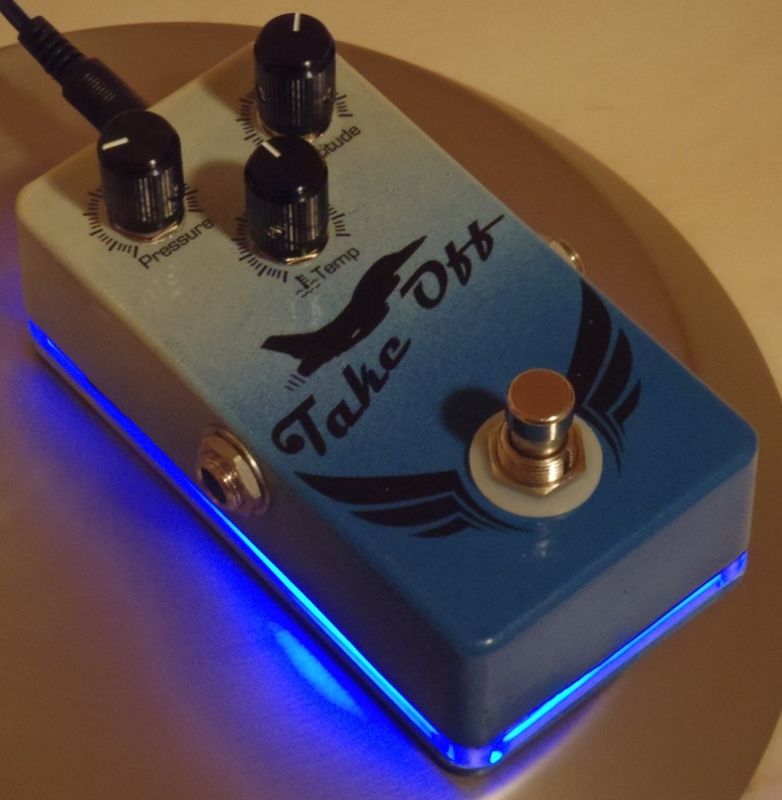
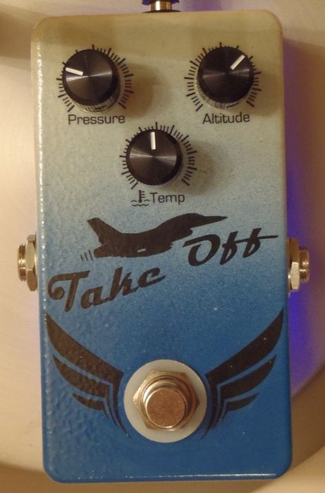
The first one I finished was my Echoplex Plus, which is the Fatpants and I stuck in a 1590A enclosure.  Next I completed a Onsie fuzz pcb that I got from culturejam.  Then today I finished my Take Off pedal, which is a Runt. Strangely enough, the baby board pcb is the only one I put into a 1590B enclosure... oh well.

I am much too embarassed to post gut shots of my rat's nest inside, and looking at some of the great enclosures lots of you guys make, I'm a bit ashamed of my own. But I'm just happy enough that they work!  Here's the pics:

The Onesie Fuzz, the LED is supposed to be "ultra violet" but it mostly looks bluish. I got the painted enclosure from PPP.


The Echoplex Plus I really wanted to use one of those clear pots and knobs!  Painted the enclosure myself and tried to create a speckle/sparkle finish with silver paint.


Lastly the Take Off / Runt PCB, this is my first attempt at painting a gradient which I thought went ok, but is still a bit grainier than I'd like.  I also used a light plate and the pedal glows red when bypassed and blue when engaged.


#5
Tech Help - Projects Page / Re: Low volume Runt
May 24, 2012, 01:22:48 AM
It is finished and working beautifully now!  D1 was a faulty part, it conducts both ways and I assume it was shunting a lot of the signal to ground.  I've replaced it with a spare and the circuit is working great, and I've just finished boxing it.

Thank you all for your help, especially mgwhit: you sir are a gentleman and a scholar.  I sure have learned a lot through this troubleshooting, hopefully someday I will be experienced enough to help out newbies myself.

I'm putting up my first build report now, whoohoo!
#6
Tech Help - Projects Page / Re: Low volume Runt
May 23, 2012, 02:53:17 AM
I pulled one side of D1, and the output volume jumped like crazy.  It sounds essentially the same as before, only with adequate volume.  So can I infer from this that specifically D1 is bad, or just that one of the diodes isn't working correctly?
#7
Tech Help - Projects Page / Re: Low volume Runt
May 22, 2012, 11:50:33 PM
OK, replacing C7 changed the tonal character a little bit at the positive lug, but no overall change.  Same problem, and the volume drops considerably across C7.  I measured it with my MM before I put it in, and it was reading ~5.1 uF, so a bit higher than it should be.

So that makes you suspect one of the diodes is a problem?  How would I go about confirming that and pinpointing which one?  FYI the effect sounds great when I attach the positive probe to lug 3 of the gain pot, I just can't get that to the output jack it seems  :-\
#8
Tech Help - Projects Page / Re: Low volume Runt
May 22, 2012, 10:49:05 PM
The sweep of the Cut pot doesn't affect lug 3 to my ears.

Pin 6 is blow your eardrums out loud.  R6 tames it down a bit, but still quite loud.  C7 kills it to nothingness.  I'm going to replace C7 and see if that fixes it.  I will report shortly!
#9
Tech Help - Projects Page / Re: Low volume Runt
May 22, 2012, 09:01:16 PM
OK, so R7 is definitely the right value, it's a Vishay 1k5 that I've double checked the number on the part as well as tested the rest of them I ordered.

The negative side of C7 is the same as the output signal, and the positive side of it is very loud and clear.

I appreciate the help!
#10
Tech Help - Projects Page / Re: Low volume Runt
May 22, 2012, 06:23:39 PM
OK, I've built the audio probe and have been probing like crazy.  I know just enough about this stuff to get into trouble, so I'll put my results up and perhaps someone more experienced than myself can help me diagnose the problem.

Lug 3 of the Cut pot:  Same signal as the output, low volume effected.  Adjusting the pot makes no change in the sound

Pin 6 of the IC:  Louder than the output with more low end, not as clear or bright as the output.

Q1 Gate: Same as output
Q1 Source: Identical to the gate
Q1 Drain:  Louder than the input signal sounds like Pin 6 of the IC

Other observations: When the positive of the probe is not connected, I can hear the effected signal.  When I touch the probe to the casing of the gain pot the signal is much louder and clearer than the output signal.  Lug one of the gain pot is incredibly loud and a bit muddy. (this was done with the gain on full)  I also notice that touching lug 1 of the gain pot, makes the effect seem to function correctly when the positive of the probe is disconnected!

My inexpert guess:  Due to the casing of the gain pot, could a bad pot putting signal to ground be causing this?

I hope this helps, thank you all for your assistance so far.  I feel like I must be getting close to the root of the problem!
#11
Tech Help - Projects Page / Re: Low volume Runt
May 21, 2012, 09:56:33 PM
Ok, I've since found a couple of resistors that were reading ~55k when they should be 100ks, and I've replaced them.  However no change yet.  I've taken pictures, I hope they help:


#12
Tech Help - Projects Page / Re: Low volume Runt
May 21, 2012, 08:34:23 PM
So I'm trying to debug again tonight, and while I was rechecking everything again I noticed that I do in fact have a part substitution.  For C9, the 1 uF capacitors I ordered are electrolytic caps, and are polarized.  The schematic shows a non-polarized cap in there for C9.  After looking at the schematic I oriented the cap negative "up", or facing towards the volume pot lug #3.

Which brings me to the question, could this be causing the problem?  Is it important that the cap there is non-polarized?  Or perhaps I have wired it in backwards?

Anyhow, that's the only thing I have found so far, even if it isn't the problem.  I'm off to make an audio probe now and take some pictures!

Thanks all!
#13
Tech Help - Projects Page / Re: Low volume Runt
May 21, 2012, 04:28:47 AM
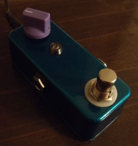
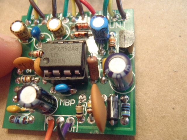
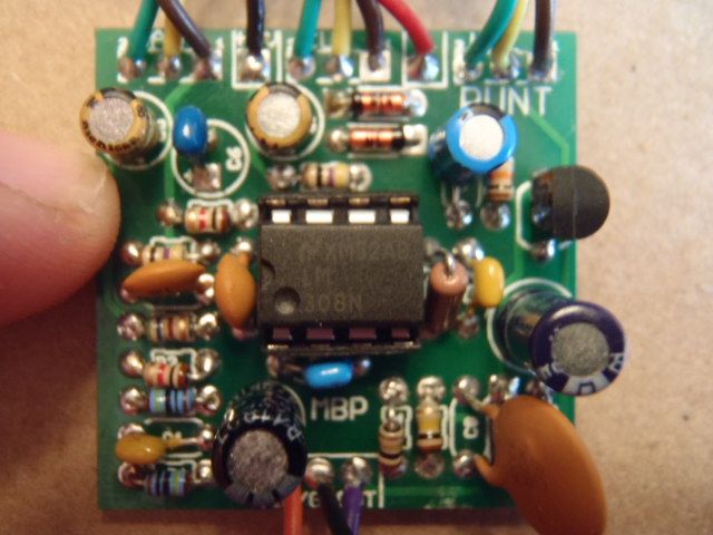
 :-[ you're right, I alternated the pins on the IC.  So if I got the pin #s right the correct order would be:
1-8: 8.27, 4.5, 4.04, 0, 32 mV, 4.5, 8.91, 4.61

I am using a 2n5457 ordered from smallbear I believe.  Unfortunately if it is the transistor, I'm going to have to wait until I order another one to swap it out.  I only have a spare J201 and an old NTE85.

I'll try to get some pictures posted tomorrow afternoon and hopefully that will help.  Thanks!
#14
Tech Help - Projects Page / Low volume Runt
May 21, 2012, 02:17:16 AM
I'm having some problems with a Madbean Runt build.

The issue is that the output volume of the engaged effect is very low.  With the gain and volume all the way up, it's still not nearly as loud as the bypassed signal.  The effect does work though, all of the pots operate as they should and it sounds correct, just at very low volume.

It worked briefly at the correct volume when I first tested it, however I had wired up the LED backwards.  After I rewired the LED the correct way, it now is at very low volume.  I've quadruple checked all of the joints that i changed for the LED, and I see no problem with them.  I've even completely removed the LED from the circuit to check if that was causing an issue, and there's no change.  I'm guessing that the timing was just a coincidence.

I have double checked my parts values and orientation, as well as reflowed any joints that I thought might have been suspect.  I've triple checked the wiring and it is wired correctly.  My guess is that a part isn't working correctly, but I'm not sure how to narrow it down to the problem.  For some reason, my gut is telling me that it might be the Q1 transistor however this is just a guess and I'm not sure how to check that with my meter.

I have used all stock parts except I have dropped my CLR for the LED down to 1k.

Here are my voltage measurements:
Positive lead at jack/battery. = 8.96
9V in at board = 8.96
Ground in at board = 14 mV
IC pins 1 through 8 = 8.27, 4.61, 4.5, 8.91, 4.04, 4.5, 0, 32 mV
Each pin of transistor = D 8.91, S 5.48, G 4.04

If needed, I can post some pictures tomorrow.  Thanks for any help you might be able to give, I'm starting to pull my hair out over this thing!
#15
Great! Looking at the specs for the LED I bought they share a common cathode.  Just what I needed to know, thanks!

Now does anybody know why on the standard wiring pdf the bottom left corner lug isn't just left open?  With my very limited knowledge, isn't it unnecessary?  With all the effort on star grounding, doesn't it make a tiny little ground loop with the lug above it when in bypass?  (probably so small it's irrelevant, but I'm curious...) Or am I way off base here?