News:

Forum may be experiencing issues.

Main Menu
Menu

Show posts

This section allows you to view all posts made by this member. Note that you can only see posts made in areas you currently have access to.

Show posts Menu

Messages - ongon

#1
Problem Solved

I read through many forums and I'm not the only person with that problem. But now my Angel Chorus is working!

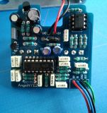
I've heard that the seller has received new PT2399 as they are known as being problematic. With the last centralised buying I ordered some spare parts for my Angel. Switching the PT2399 finally worked and solved the problem. It looks like the new PT2399 get some QA as every pack is labelled. Two friends ordered the same Chorus and built it without that problem too (all those PT2399 included are labelled too).

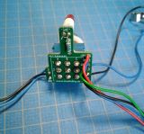
It took quite a time but finally it's working. The chorus is boxed, painted, mounted and in use now! It sounds great. Thank you for all of your help and support!  :)
#2
After I had some time, here's another update:

I asked a colleague for some help. He plugged it to an oscilloscope: Even without an instrument it was possible to see the difference between working effect (waves etc.) and broken (clean, almost strait line). Unfortunately there was no obvious reason for the problem. Also cleaned the board and checked the IC's.

The effect works sometimes: After some replugs of the power supply it's maybe working, maybe not. And vice versa: If it's not working it works sometimes after reconnecting the DC power some times.

At least it's not caused by the power supply unit, as I've tested it with a different one too.


Btw. what is the best way to use the audioprobe here?
#3
So, here's an update:

Rewiring

I have pulled out each wire and resoldered it. After this everything was Ok (once more …); LED was steady now, effect working, VR1 at normal temperature. To be sure, I unplugged the power supply, and replugged it. Well, again it's not working correctly, same symptoms. It's still out of the box btw..

Measured Value

Measured values of the PT2339 (GND on the board to the Pin).


  • P1: 5,82 Ω

  • P1: 6,20 V – without PT2399 inserted
  • P2: 3,0 - 3,6 V – without PT2399 inserted

  • P1: 6,22 V – PT2399 inserted
  • P2: 3,31 V – PT2399 inserted


At least it's not the boxing …
Looking for a suitable capacitor for the probe atm.
#4
QuoteYou could remove the power source, take the PT2399 out of its socket, and test the resistance from the +6V point to ground. This is often a way of finding shorts or low-resistance paths to ground that will draw too much current.

[...]

Audio probing at the input to the PT2399 (pin 16) and output (pin 14) will isolate the problem to before, inside, or after the PT2399.
Thanks, I'll try this and report back.

QuoteI think the only LED in the circuit is the status (bypass) LED. Here, that should always just be on or off. It shouldn't have been blinking, that indicates a bad connection somewhere.
Now, as you say it ...
I expected it to be intentional because it was blinking when the rest was Ok, but steady with the problem. But yes, you are completely right here.


QuoteThe regulator should get warm (but not hot). That's normal.

Also, check the voltage on pins 1 and 2 of the 2399. Those should be +6v and +3v, respectively.

Thanks, I'll check this.
#5
QuoteI have no idea why a pot would be getting noticeably warm, but...

I don't think all PT2339 chips will be okay running VCC at +6V for a long period of time. Datasheet says it can got to +6.5V as an "absolute maximum", but the recommended max is +5.5V. I would imagine there are some 2399s out there that would die after a while at +6V.
It's not the poti, but the 78L06 (6V positive voltage regulator; VR1 in the schematic).

The 5.2V looked very high to me too. But as it's still below the absolute maximum, I don't know if this is somehow intentional.


QuoteCulturejam brings up a good point. There isn't a 5v regulator? What is the voltage coming out of it?

I guess you can test the 2399 with an audio probe and see if the audio is coming in and out of it.

There's a 6 V regulator (the one getting warm mentioned above). I'll have a look on such a probe, seems reasonable to me. Thanks for that hint btw..
Stupid question, but there are 5 output pins, which one do I have to measure? (See PT2399 Manual, p. 3).

QuoteAre the backs of your pots insulated from the solder side of the circuit board?  Use foam tape or something. Leaving an air space isn't enough because the pots may move when boxed.

Yes, each one as a bumper on it's back to prevent this. At the moment the board is out of the box and I also kept enough air between it and the poti's back. At the first mounting it's possible that one soldering got a contact by poking through the border of the bumper, but afterwards this shouldn't be a problem. Just to be safe I'll put some tape insulating tape on the bumper before the next boxing; certainly I need to fix the circuit before the next try …


QuoteWhen a circuit behaves differently when boxed, it usually means that something was mechanically disturbed and is either making contact where it shouldn't (shorting), or breaking a contact, like a loose wire or cold solder joint.

Is there some way to find out where this could happen? Unfortunately removing the box doesn't fix the problem and I already resoldered the potis and cables. But maybe it's a good idea to completely rewire these parts as drezdn mentioned. I'll try this.


QuoteIn a 9V-powered circuit, the way for a component to get warm is to have a short or resistance of less than a few hundred ohms between 9V and ground. (Power = V^2/R, so to dissipate more than a small fraction of a watt, R must be less than 300 ohms or so.) VR1 is a 100K pot, so there is some connection out of place that is shorting it, or the actual pot is shorted (but usually IME if you overheat a pot they fail open-circuit rather than short). Or it's touching something else that is hot, but that is unlikely since it's on the opposite side of the board.

VR1 is a voltage regulator, do you mean P1 (Poti) instead? (Or misunderstanding on my side). Haven't (visually) found something that could create a short on the board so far. But I'll check the wiring again and also have a look on the footswitch board (just to be sure).

Btw. the LED lights steady, but blinked when everything was ok; maybe that's another hint towards a short somewhere (but where?).
#6
Yes, there's an isulation by a bumper, and at the moment they are mounted far enough. Unfortunately I don't have another IC around. Can I verify that mine is working?
#7
Quote
I'm lazy sometimes, so when a board works outside of the box, but not in it... I'll take the board out and just rewire the whole thing.

I have checked and resoldered all cables, hope this comes close to a complete rewire.

QuoteCould you post a few clear pictures of how it is wired in the box?

It's out of the box at the moment, as it isn't working there either. There are images of the board (front / back) and the switch board:


The jacks are soldered (as in the Installation Guide):


  • Ground (black) on the inner connector
  • Signal (blue) on the outer connector
#8
I have (almost) successfully finished the Angel Chorus, tested it and then put it into the case. Unfortunately after the latter, it's no longer working correctly. I got it working again (out of case) but after putting it into again, it's not working – with the same symptoms.

Documents

The Problem

The Bybass is working, but switching the effect on leaves a clean (but slightly modified) signal. Both Potis don't have any effect either.

Also noticed:


  • If effect is ON, VR1 becomes notably warm
  • The LED is steady, but was flashing when the effect was wokred correctly


Trying to fix


  • Visually checked the solderings
  • Test with / without case
  • Test with / without LED
  • Compared each Components orientation and value to the scematics
  • Refreshed some solderings
  • Refreshed all solderings of movable or possible stressed parts (potis, cables etc.)
  • Took some breaks and drank some coffee

I'm not quite sure, but possible a soldering stabbed through a poti bumper and got a contact, after mounted into the case. But after the first (failing) test this is not possible any longer.

What I did so far (short version)


  • Soldered the components and wired the footswitch, jackets etc. --> First Test: Working
  • Put it into case --> Test again: Not working
  • Pulled it out of case, fixed a potential bad soldering --> Test again: Working
  • Put it back into case --> Test again: Not working
  • Pulled it out of case --> Still not working


What I did so far (long version)

After doing the soldering of all components I wired the jacks etc., except the LED on the 3PDB Board. A first test was successfully and everything was working as expected. This changed after I put everything into the case and the problem as described above occurred. So took everything out again, but still no effect or changes through poti; removed the LED too (was easier dismount anyway).

Afterwards I have checked every component and compared it's value respectively orientation to the schematics. I found a potential short by a small soldering drop and cleaned it up. Also soldered a new LED for testing. The next test (still no case) was successfully; chorus was hearable and both poti's had effect on the sound. The LED was flashing and VR1 at normal temperature.

I then once again mounted the board and jacks into to case on once again the same problem. Steady LED, VR1 got warm and no effect. Dismounted again, but still not working.


Modifications

I used another 10 kOhm Resistor for R11, as i couldn't find the original.


Update

IC1 wasn't fully into it's socket, but no change by this.

Update – IC VCC Values/color]

Measured GND (board) and IC VCC Pin.


  • PT2399 (IC2): 6.20 V