
Ahhh you're too kind, dude. Thanks so much for the like and share!
- Welcome to madbeanpedals::forum.
This section allows you to view all posts made by this member. Note that you can only see posts made in areas you currently have access to.
#2
Build Reports / Buzz Box Original Fuzz Design
August 08, 2017, 10:21:19 AM
It took me long enough, but here's my first finished design from top to bottom. Quite a simple schematic, not particularly based on anything and I'm pretty happy with it!
See what you think!
Video:
https://www.youtube.com/watch?v=VqUlyEowUzE&t=3s

See what you think!
Video:
https://www.youtube.com/watch?v=VqUlyEowUzE&t=3s
#3
General Questions / Implementing a Tape Deck Saturation Schematic
March 30, 2017, 09:59:36 AM
So my mate picked up this sony tc-133 tape recorder/player box, and its a bit shoddy but, man.
When you clip this thing it gives a great smooth distortion/saturation which'd be great for a guitar pedal, the only problem is.. I don't understand a lick of it. I wouldn't expect a great deal of people here too either..

https://ibb.co/iid7ka
I've heard transformers can do some great saturation sounds, but I have no idea if that's whats causing it in this case. I'm interested to know whats actually clipping and distorting so nicely, and see if it can be applied in a pedal (even it was over 9v).
Not sure what more information you'd need so, if there's anyone who can decipher this mystery, it would be very educational.
Cheers
When you clip this thing it gives a great smooth distortion/saturation which'd be great for a guitar pedal, the only problem is.. I don't understand a lick of it. I wouldn't expect a great deal of people here too either..
https://ibb.co/iid7ka
I've heard transformers can do some great saturation sounds, but I have no idea if that's whats causing it in this case. I'm interested to know whats actually clipping and distorting so nicely, and see if it can be applied in a pedal (even it was over 9v).
Not sure what more information you'd need so, if there's anyone who can decipher this mystery, it would be very educational.
Cheers
#4
General Questions / Re: Drive Pedal - Impedance issue?
March 26, 2017, 01:37:45 AM
Yes, that signal chain is right. I did not try other pedals at the time I had that breadboarded, but I will try it. I've tried this flanger with a big muff before and it seemed to handle it a lot better than this. Most likely input impedance is higher on a big muff, which is what makes me think that's the issue.
My problem is that now I have added a buffer, I can't seem to create a low pass, which was to roll off some of the high freq content of the flanger. Either that, or there is something seriously wrong with the impedance relative from the output of the buffer to the input of the boost. I guess my question is to ask if that is the case? would impedance cause that "harshness" issue? how can I alter it?
Not expecting any big paragraphs - Links are always helpful!
#5
General Questions / Re: Drive Pedal - Impedance issue?
March 24, 2017, 03:21:54 PM
Hi guys, thanks for the replies. Just a little note, I am breadboarding this with the buffer preceding the drive/voltage divider biased transistor.
I did add a 10k resistor with the 10nf cap making the corner freq roughly 1.6kHz, this works fine without the flanger engaged, and it did before. But the issue is when the flanger is turned on, it seems to completely ignore the filter, this is where I thought the buffer would help. If I try this 10k/10nf combination after the buffer, the cutoff is basically nullified, or at least changed drastically. So I'm wondering the correct place to filter out the harsh frequencies of the flanger, whilst also filtering out the same frequencies on the guitar without flanger.
To put it simply, the drive sounds harsh with the flanger engaged, I'm going to try and upload a sound sample which should make this a lot clearer.
EDIT:
So here is the drive with no buffer
https://www.dropbox.com/s/3g1vgzpk1d6hxs3/Flanger%20Impedance.mp3?dl=0
Here is the drive with the buffer,
https://www.dropbox.com/s/apzgox0rduoqlio/Buffer%20Drive.mp3?dl=0
-After the buffer stage is a 4.7uf cap (purely for dc blocking purposes) followed by..
-Low pass : a 22k Resistor and then the 10nf cap to ground. According to AMZ R-C Filter calculator this rolls off at 723hz Followed by..
-High pass : 10nf cap into the drive stage
I'm using a strat, and I believe single coils should have an output impedance of about 6-7k, so a resistor of the same value should have done nicely? but I tried going more extreme to demonstrate the problem.
The buffer has definitely let the flanger signal in nicely, but I don't think the buffered drive is meant to be so sharp/harsh, this is what I'm having problems with. It seems to ignore the low pass filter, even though the high pass works fine. I'm very happy with the sound of the unbuffered drive, but I'd like it to work with my flanger, hence the buffer issue.
#6
General Questions / Re: Drive Pedal - Impedance issue?
March 23, 2017, 10:11:25 PM
My intention was to be able to severely smooth over the harsh frequencies in the guitar signal, and cut the bottom end (C1/C2). With the flanger pedal active in front, it doesn't at all, and ruins the tone of the drive completely. Almost like it was ignoring the low pass (C1).
#7
General Questions / Drive Pedal - Impedance issue?
March 23, 2017, 08:22:42 PM
So a quick introduction on what I'm working on, you'll see some similarities in the design to a rangemaster. Although this isn't built to be a boost pedal at the start of a chain, this is to offer a drive at the end of my pedal chain, as an alternative to an amp overdrive. I felt I could customize a lot more how my signal is being driven this way and just have a nice touch of distortion over everything to add colour, like a cranked valve amp, but with a couple adjustments to frequency response.
So what I have is sort of a slightly cocked wah/bandpass fuzzy driven overdrive, I suppose. Here's the simply drawn schematic -

This works great when my guitar goes straight into it. However since this is going at the end of my pedal chain, I thought I'd test it with another effects pedal that I use - "Mooer Elec Lady" flanger. Like I said the drive is last in the chain so the signal goes to the flanger and THEN the drive. So when I turn the flanger on, I get a very nasty high end distortion ruining the tone of the drive completely. If you notice the drive design it has a 10nf cap grounded to make a low pass filter before anything else can be affected, so I'm a bit confused. I thought it may be an impedance issue, so I added a buffer, the TS9 input buffer to be exact..
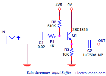
The issue I had with this, is after the buffer, I add in the 10nf cap to ground and it really doesn't change the frequency response much at all, even after trying a 10uf cap to ground just to test it wasn't my breadboard, it just reduces the volume more than anything really, not much change in the frequencies. I'm looking for a way to solve/understand whats happening.
I tried to add the drive circuit in anyway, I needed to add a resistor in the signal chain of about 20k to feed the correct amount of signal into the drive transistor, and it does help some what, but I can no longer make a low pass/high pass filter like I did in the original design, or at least, don't know how to rectify the signal to be able to do so.
I'm somewhat uneducated on the actual theory of electronics so I thought I'd ask to see what the issue might be. I can upload some sound samples if necessary.
I'm using BC109 transistors by the way!
Thanks for your time!
So what I have is sort of a slightly cocked wah/bandpass fuzzy driven overdrive, I suppose. Here's the simply drawn schematic -
This works great when my guitar goes straight into it. However since this is going at the end of my pedal chain, I thought I'd test it with another effects pedal that I use - "Mooer Elec Lady" flanger. Like I said the drive is last in the chain so the signal goes to the flanger and THEN the drive. So when I turn the flanger on, I get a very nasty high end distortion ruining the tone of the drive completely. If you notice the drive design it has a 10nf cap grounded to make a low pass filter before anything else can be affected, so I'm a bit confused. I thought it may be an impedance issue, so I added a buffer, the TS9 input buffer to be exact..
The issue I had with this, is after the buffer, I add in the 10nf cap to ground and it really doesn't change the frequency response much at all, even after trying a 10uf cap to ground just to test it wasn't my breadboard, it just reduces the volume more than anything really, not much change in the frequencies. I'm looking for a way to solve/understand whats happening.
I tried to add the drive circuit in anyway, I needed to add a resistor in the signal chain of about 20k to feed the correct amount of signal into the drive transistor, and it does help some what, but I can no longer make a low pass/high pass filter like I did in the original design, or at least, don't know how to rectify the signal to be able to do so.
I'm somewhat uneducated on the actual theory of electronics so I thought I'd ask to see what the issue might be. I can upload some sound samples if necessary.
I'm using BC109 transistors by the way!
Thanks for your time!
#8
General Questions / Enclosures - (Alternative options, sheet metal, etc)
February 11, 2017, 12:09:45 AM
So the standard hammond 1590b and 1590bb are just too plain and overused to my eye. I've been searching around everywhere for sheet metal enclosures and just generally enclosures with different looks to them. I've found a few sheet metal enclosures, but they aren't really the dimensions I'm looking for. I actually wouldn't even mind an enclosure like the 1590bb with a bit more height and much less rounded edges, something a bit different to the norm..
Is there any direction/website you guys can point me to?
I am UK based, by the way.
Is there any direction/website you guys can point me to?
I am UK based, by the way.
#9
How Do I? Beginner's Paradise. / Re: Silicon Fuzz Face - OSCILLATION
January 12, 2017, 03:59:34 PM
Well I think the fact there is no oscillation when its unplugged says alot. I believe two of the lugs aren't meant to be connected on one jack which are, so I'm going to swap that jack and see how it goes. I've also got my transistors today, AC128K and BC108.
Edit:
So I did the tests mjg said, I think they were what midwayfair was trying to say, I just got a bit confused. The youtube vid I linked says it all really - faulty jack, a lug was linked to another, and I think I had my jacks wired wrong anyway. I sorted the wiring, changed the faulty jack, and bam!
Silicon FF (bias is a bit off, but easy fix) -
https://www.dropbox.com/s/g9v65q0sg2r272f/Si%20FF.mp3?dl=0
Thanks so much for your help, I would have never figured this out - I'm still a beginner.
#10
How Do I? Beginner's Paradise. / Re: Silicon Fuzz Face - OSCILLATION
January 11, 2017, 10:48:21 PM
I think I'm a bit unsure on if you meant cable or jack socket in the test you mentioned, did you mean on the tip of jack cable when its plugged in the jack socket? is there any link you can show me? But I did try alot of different things based around that but didn't get any beeping. I'll probably look more into that tomorrow, as its getting late here.
Is this the sort of test I should do? - https://www.youtube.com/watch?v=nxhSotfKZEE
I looked up the receipt for the jacks they were on ebay, it was labelled switchcraft stereo but theres no link available for it.
I did a little test on the jack lugs which might be useful info, and heres a closer look at them -
https://www.dropbox.com/s/c7fhdr3ubiy988g/20170111_214621.jpg?dl=0
https://www.dropbox.com/s/itsflm0nppo3a50/20170111_214705.jpg?dl=0
I shifted both the wires (red on the right, black in the middle - according to picture 1) I shifted them both left. So now the red would be in the middle and the black on the left.
I got signal, but oscillation still. I unconnected the input jack and the oscillation stopped again like before. I also tried black wire on the left lug and red on the right, but got nothing coming through.
This is all with the original silicon FF circuit like schematic on the first post.
Edit: I watched the youtube link I posted and did the same sort of test. Turns out one of the jacks beeped when I touched the ground lug and a lug which wasn't ground, it wasn't the input lug, but the one that isn't connected in the pics. (Sorry I'm confused with what lugs are labelled what at the minute haha)
The other jack didn't do that, so I'm going to assume that they're not meant to be connected?
I have another jack spare so I'll get testing it tomorrow
#11
How Do I? Beginner's Paradise. / Re: Silicon Fuzz Face - OSCILLATION
January 11, 2017, 07:33:19 PM
So at the moment I have only 3 jacks, two stereo which I'm using and have used for the perf, I just snipped the wires *I'll deal with it later*. They were on an enclosure just for shielding purposes, but I removed them for the pic.The ground on both jacks are connected to the ground bus on the breadboard, the red wire you see is connected the same on both jacks - connected to the input/output caps.
Something suggests to me the ground wire is wrong?
*Ignore the bad soldering it was my first time*
The third lug has solder/wire on it too from when I tested it as ground, though I could have tested it wrong since I was trying a million things at once..
https://www.dropbox.com/s/z3pc0qcqbkhzyvt/20170111_192438.jpg?dl=0
This pic shows where the red and black wire connects to the breadboard (to the output cap and ground bus)
https://www.dropbox.com/s/3iguihlmqmbax2e/20170111_192451.jpg?dl=0
#12
How Do I? Beginner's Paradise. / Re: Silicon Fuzz Face - OSCILLATION
January 11, 2017, 05:10:40 PM
So I've rebuilt the circuit on breadboard (with 2n4401s and a 1uf input cap).
I tried the 100k resistor across the Q1 collector and base and got this squelching ---
https://www.dropbox.com/s/nvw416wndydjw27/Oscillation%202.mp3?dl=0
There is no oscillation if the jack input isn't connected, and no signal whatsoever when grounded. This was the same when I tried the normal FF, and then the 100k resistor swap.
And of course, I tried the cap between the collector and base (2200pf) got rid of some squealing on some settings but lost a ton of gain (not really any distortion just saturated mush) and it returned at a lower pitch if I fiddled with the pot. These aren't dolphin noises, but I'll either get them, or this squealing in most fuzzes I've tried. I've probably tried in the range of 7-10 different circuits with pretty much these results.
#13
How Do I? Beginner's Paradise. / Re: Silicon Fuzz Face - OSCILLATION
January 10, 2017, 09:47:29 PM
The perfboard is laid out terrible, as I really just did wack it together as I went along. But I know its not done wrong/any different to the breadboard, cause the noises are identical to when it was on breadboard. When I tested if it was a ground lug wired wrong, I swapped the ground wire to another lug and got no guitar signal coming through, but still a squealing noise, I don't know if that means anything...
I did also flip the transistors when it was on breadboard, I think I can remember it just having little to no gain, and swapped transistors a few times (2n2222 and 2n4401) but I will try this again aswell as the other ideas.
I did also flip the transistors when it was on breadboard, I think I can remember it just having little to no gain, and swapped transistors a few times (2n2222 and 2n4401) but I will try this again aswell as the other ideas.
#14
How Do I? Beginner's Paradise. / Re: Silicon Fuzz Face - OSCILLATION
January 10, 2017, 08:30:34 PM
Hey Ralf, I don't have an audio probe unfortunately  I have tried using these transistors on their own, and they work, but never when I've had more than one on a circuit, that's when I get oscillation. I've tried a few different fuzzes with them and had the same result.
I have tried using these transistors on their own, and they work, but never when I've had more than one on a circuit, that's when I get oscillation. I've tried a few different fuzzes with them and had the same result.
#15
How Do I? Beginner's Paradise. / Re: Silicon Fuzz Face - OSCILLATION
January 10, 2017, 08:03:29 PM
So I tried swapping the ground lug wiring and got just squealing with no guitar coming through.. So obviously that can't be it. Would it make a difference if i was using the right or left input?