News:

Forum may be experiencing issues.

Main Menu
Menu

Show posts

This section allows you to view all posts made by this member. Note that you can only see posts made in areas you currently have access to.

Show posts Menu

Messages - YeastLords

#1
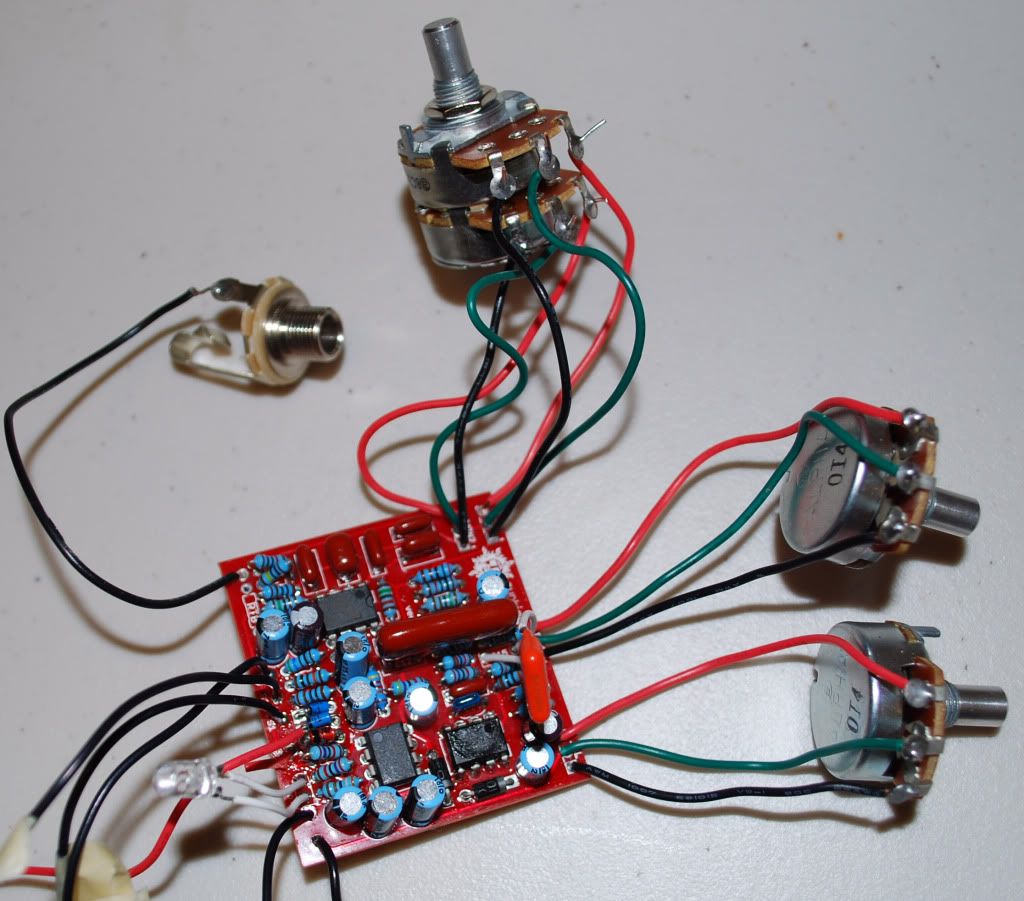
IT WORKS!!!  Reversed the wiring on my volume and tone pots, hooked up the ground to the sleeves of my in/out and I couldn't be happier.  You guys are awesome and I would totally high-five you all if you were here...  My neighbors on the other hand do not appreciate your help, as I had my amp cranking the tubes to the point of break-up for at least an hour.

Thanks again everyone!
#2
One more question... my testing switch is a DPDT On-Off-On.  Is this okay, or does it need to be on-on-on.  It's not a foot switch.
#3
Quote from: jkokura on March 22, 2011, 09:30:52 PM
Which charge pump are you using? Does it end with CPA or SCPA? It should be the latter.

Jacob

I ordered the SCPA model, but when I got the charge pump, I could only see CPA printed on it... I wasn't sure if it was because the "S" wore off, or because they shipped me the wrong one.  I was also worried about this, so I ordered a TC1044SCPA that just arrived yesterday.  If these other suggestions don't get me up and going, I'm going to break out the de-soldering braid and put in the TC1044SCPA.

Thanks.
#4
Where this is my first pedal, I totally screwed this one up.  Can't wait to get home and heat up the soldering iron.  Thanks for the catch.

Quote from: petesz on March 22, 2011, 09:25:13 PM
Shouldnt there be a connection from input jack sleeve to DC jack negative? And possibly input jack sleeve to output jack sleeve?
Whenever I hear a loud buzz and nothing else it's because I forget something like this.
#5
Sweet...good info.  I think I'll just order a few of the plastic jacks so I don't have to worry about it.  Thanks again.

Quote from: madbean on March 22, 2011, 09:01:56 PM
Yeah, your gain pot is right. Everything else on the board is looking good.

I ask about the metal jack for two reasons: one, make sure you are getting 9v through to the PCB by using a DMM . Second thing is, if you are going to use a metal enclosure, that jack will have to be completely isolated from it or it will short out the power.
#6
Okay... tone and volume, I'll fix that when I get home.  What about the Gain?  I kinda used the same numbering (incorrect) scheme on all three. Actually looking at it closer, I may have unintentionally done that one right.

The DC jack is one of the metal ones.  Here's a better pic:


On the C12... Because it's so big and awkwardly placed, I've been extra careful to make sure it's not touching something, so yeah it's got plenty of clearance around it.

Thanks Brian.


Quote from: madbean on March 22, 2011, 08:19:14 PM
Your tone and volume pots are wired backwards, to start.

What type of DC jack is that you have there...is it one of those metal ones?

Also, for your big C12...are you sure the leads are not touching any of the leads of the resistors underneath?
#7
Yeah, I figure it's a grounding issue... the only problem is that I've gone over this thing with a magnifying glass several times and can't find any bridges.  It's not even in an enclosure yet, so that's not an option for shorting.  I checked polarity on all my polarized caps and they're correct.  I'm still not sure if I wired the pots backwards or not, and whether or not this would cause any problems to this extent.
#8
Tech Help - Projects Page / Sunking - BUZZZZZZZZZZZ!
March 22, 2011, 07:32:46 PM
First build... finished the sunking v3, and as the title mentions all I get is a BUZZZ noise when I plug in.  It doesn't matter if I'm hooked up to DC or not and whether or not the sunking is on or in bypass mode (I just wired it standard, not true bypass).  For testing, I've got a DPDT on-off-on switch.  LED works.  All the voltages are correct at each of the IC pins.

I'm  new to all of this, so it's probably something simple.  Here are a few pictures... if anyone notices anything out of the ordinary, any help would be much appreciated!  Also, if someone could confirm that I've wired the pots correctly, that would be great.  Sorry about the lack of color-coding/incorrect color coding on the wires... and yes, I know it looks ugly... the next one will look fan-freakin-tastic.


Thanks for any help... I can't wait to get this thing up and going.

Tyler
#9
Fortunately I'm aware of my skill-level and as a precautionary measure ordered a bunch of extra parts, the 3PDT included.  Great info on the heat sensitivity of the switch though... I'll be even more cautious when I solder the new one.

I don't want to sound repetitive on my "thank you's" but, I realize that it takes time to look at my issues and type up a response with nothing to gain on your guys' part.  So yes, thanks again!

Quote from: jkokura on March 14, 2011, 08:18:12 PM
Yes, your switch is wired incorrectly.

You need to turn it 90 degrees. The poles in that picture connect left to right, but you have wired it to connect bottom to top.

Unsoldering a switch is something that is a little bit dangerous. It is VERY easy to heat it up too much and make the switch die on you. My recommendation is thus:

1. Use a new switch if you have one. Just cut out the old one, and then use the new one. If you don't have a new switch to use, then move on to step 2.

2. Unsolder the switch following these steps:
a) Use a little bit of heat to remove the wires. Grab one end of the wire with pliers, making sure the switch is secured to something, and then use your soldering iron to heat up the lug. Pull the wire as you do so, until it come off the switch. Remove heat immediately. It should only take seconds, so if it's taking too long, don't heat the switch lug anymore, let it cool down and look at why the wire isn't coming away from the switch easily and quickly. If it's because the Solder isn't melting quickly, come back and let me know and I'll tell you what you can do.
b) Let the switch cool for 1 minute. Get a timer out. Really, let the switch cool.
c) move on to the next lug, repeating step a.
d) once all the wires have been removed, and the switch is empty, each lug will still have solder on it. We need to remove that. There are multiple ways of doing this, but if you have no experience whatsoever, go watch at least 5 videos on different methods for 'desoldering'. Pick one that you think will work, and then practice it if you can. Once you feel you can remove solder from the switch, do so one lug at a time. Again, make sure that you let the lug cool down after you've removed the solder. Removing solder will take a little bit longer, but depending on your method, you probably won't need as much heat, so it should work okay. I'm usually able to rescue 7 out of 8 switches using the copper wicking desoldering method.

Come back if you have more questions, but this should get you on your way.

Jacob

Quote from: gtr2 on March 14, 2011, 08:36:58 PM
Jacob is right on as usual!

Soldering is easy, but desoldering takes some wicked skill!  I'll reiterate Jacobs post "TAKE YOUR TIME"

Also when soldering, you really don't need all that much solder.  Heat up the parts and let the solder "suck in"  there shouldn't be globs.

Best of luck!  Hopefully you'll have a working sunking soon  :)

josh
#10
You guys are great.  Can't wait to get home from work so I can start on this again.

Okay, so here's a picture of my more-than-likely incorrectly wired 3PDT   
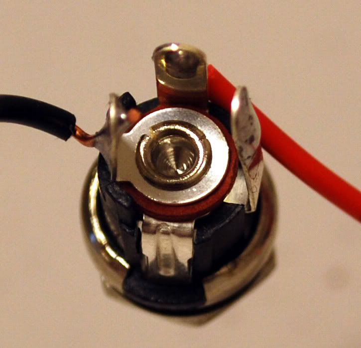
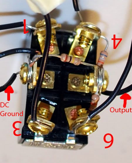
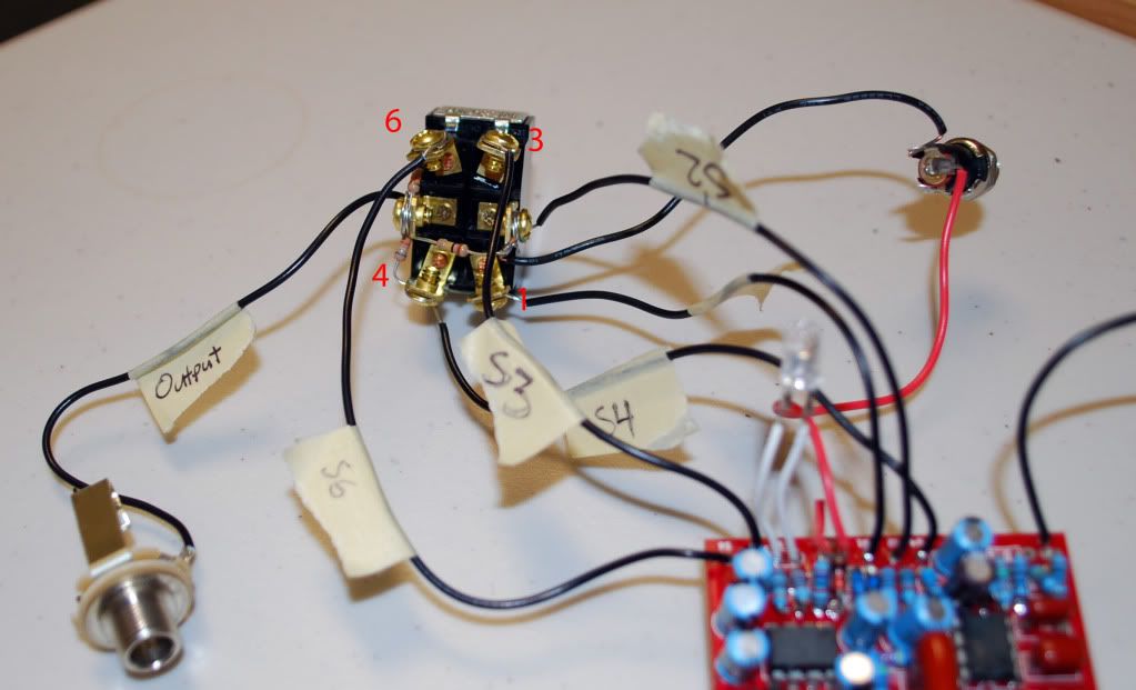
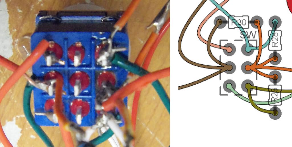
I think I understood your "tunnel" description, just want someone to confirm that I've done it wrong by the picture.  If so, cursed be manufacturer of this switch by printing a number "3" in the opposite orientation of your description.   

Okay, so no jumper under resistor #9.  Why is that damn hole there?!  Arghh.. probably to appropriately discourage newbs like me from taking on these types of projects.

Thanks again guys.


Quote from: jkokura on March 14, 2011, 07:31:08 PM
Welcome to the forum! Great post, you gave us lots of info. I like.

3) Doesn't matter. As long as each 3-in-a-row is attached to the same 3-in-a-row on the pot, it doesn't matter if it's the top or bottom, they're interchangeable.

4) Yes, it could be, but it may not be. The reason we use a stereo jack on the input is so that the battery gets 'turned off' when you unplug the input cord. All it would mean is that you would always be draining the battery. Use a stereo jack if you don't want your battery to run out too quick.

5) Always use the right build documents for your build. If you have a V3 board, use the V3 documentation. Don't worry about what V2 or V1, or even V4 might say, only worry about the V3 documents. It might be that this jumper you added is the source of your problems, I don't remember there being any jumpers in the Sunking. In fact, there isn't, so if you installed a jumper that should be removed.

6) Proper orientation for the 3PDT would be so that the lugs form a 'tunnel'. That is to say, that when looking at one pole, you can see through all three of them. So orient the switch with the lugs with the holes up and down. Yes, you leave the middle pole alone in this build. The sunking is a buffered effect which only needs a 2PDT switch. When you use a 3PDT you won't need that third pole, which is why the documents say to leave the middle pole alone. Make sense?

Hope I've helped. Pictures can help us out.

Jacob

#11
Wow, thanks for the info!  I really appreciate it. 

I have a couple of comments/questions regarding:

3) So it looks like I "guessed" the lug numbering correctly; however I'm still making assumptions on what is Gain1 and what is Gain2.  My assumption is that when looking at the pot from the top (ie... from the side that I'll connect the knob to) is that the top (or closest to me) "layer" is Gain1 and that the lower "layer" is Gain2.  Am I right?

4) I in fact WAS using a battery connector with my mono jack.  Maybe this in-and-of itself is the problem?

5) I thought they might be connected via the PCB trace but was confused because a) There's a hole to solder a jumper or whatever, and b) it's made mention in a previous document for a v2 sunking to "note the jumper at R9, which just so happens to be where this hole is on the v3 PCB.  Any thoughts on this?

6) Hm... I guess I remain confused on this one.  I wired it as such based on some info from Brian in the Sunking pdf that indicated, "if using a 3PDT, wire the two outside columns of lugs, leaving the middle column completely unconnected.  Which of course is where I got confused thinking, "uhm, this thing can have 4 different possible orientations."

Thanks again for any help on this.
#12
Hey Everyone... thanks in advance for taking a look at my topic.  As mentioned, this is my first build so any patience with my lack of knowledge is also appreciated.

Basically, I put together a sunking and it doesn't work.  LED doesn't illuminate, I plug it in and get a crapload of painful noise.  I checked closely for any bridges and polarity issues and didn't see anything, but here are the things in the back of my mind that have me uneasy:

1 - The parts I ordered for C12 (2n2) and C15(3n9) looked much different than I was expecting.  here's a Mouser link: http://www.mouser.com/ProductDetail/Panasonic/ECQ-U2A222KL/?qs=sGAEpiMZZMvQAn3cSZoTr%2fE8oegrb5rTBjI2DE%252b7yx4%3d

2 - The IC1 and IC2 I purchased were both TL072ACP whereas the documentation only specified TL072.  I've noticed on Mouser and Digikey there are several versions of the TL072, but my knowledge/experience isn't enough to know what those differences are and whether or not these difference would cause a problem.

3 - I wasn't sure I wired the pots correctly, particularly on the dual gang pot.  There's a place for Gain 1 and Gain 2 for the dual gang, and the PCB has a place for 1, 2, and 3.  I made assumptions on which connections were 1-3 on the pot and which of the two levels on the pot was gain 1 vs. gain 2.  

4 - I installed a mono 1/4" input jack (I've since ordered a stereo).  I wasn't sure if this mistake alone would cause the aforementioned problems in the introductory paragraph.

5 - I soldered a piece of wire between a connection underneath R9 that connects to R16, R17, and R18.  It looked like the right thing to do based on the schematic... maybe I'm wrong?

6 - I'm using a 3PDT without using the middle row.  Um.. there aren't any markings on this thing and I wasn't sure that I'm using the correct two outer rows.

7 - I didn't wire for True Bypass, and thus left off the RTB resistor from the PCB.  I don't think this is a problem, but that empty spot on the PCB with no resistor keeps staring up at me.

Any help is appreciated.  I'm going to dig back into this on my own after I take a day off from messing with this thing.