News:

Forum may be experiencing issues.

Main Menu
Menu

Show posts

This section allows you to view all posts made by this member. Note that you can only see posts made in areas you currently have access to.

Show posts Menu

Messages - Diocide

#1
Quote from: gordo on November 19, 2016, 11:47:25 PM
Gotta love the easy stuff.  That avatar is going to give me nightmares :-)

Yeah. It's kinda weird because I couldn't see any of the lugs touching each other, but as soon as I tightened the pot, it would cut out.

My avatar is from an album from a band called Black Pyramid. Awesome band.
#2
It ended up being that when I tightened down the nut on the pot, it would twist the body of the pot just enough to cause it to ground out. I held it in place while tightening and the issue seems to be resolved.
#3
Quote from: jimilee on November 14, 2016, 04:03:52 PM
Sounds like a sold bridge honestly.

It shouldn't be a big deal to undo the pots and flip up the PCB to check it out. I'll probably dot that next.
#4
Quote from: darrenw6000 on November 14, 2016, 11:13:17 AM
Did it work outside the box?

I only test prototype PCBs outside of box. I know it's a bad habit, but if it's verified, I don't bother.
#5
Here's my voltage readings on the IC.

1-4.7
2-4.7
3-2.3
4-0
5-4.6
6-4.7
7-4.7
8-9.3

I also notice that the vol pot has continuity to ground on all three terminals. Maybe the pot is not good?


#6
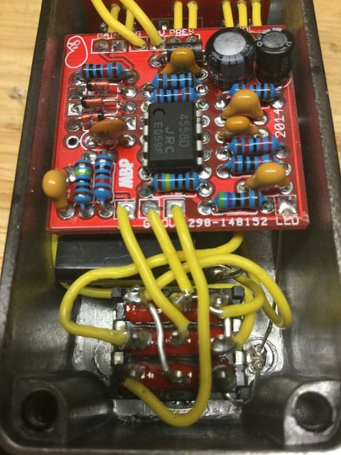
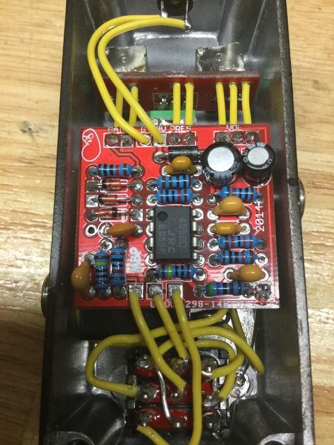
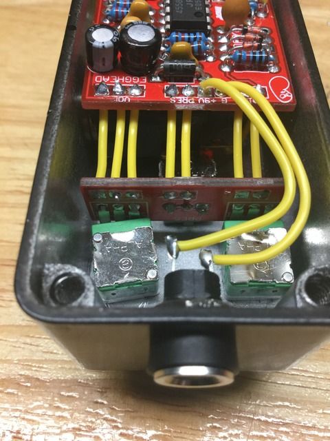
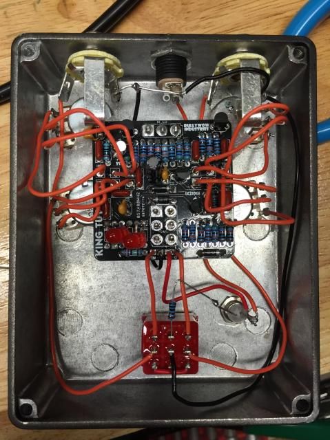
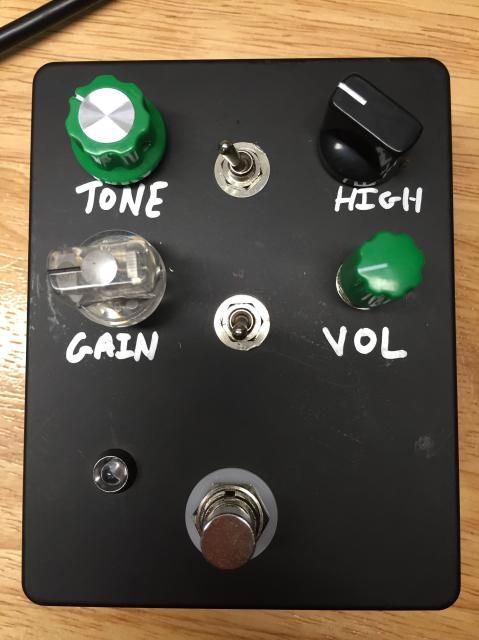
So I've built 5 1590A builds and this is the first one I'm having an issue with.

I've done due diligence and in stumped. The effect bypasses fine, but when engaged, the led lights up, but there is no sound. At all. Like not even static or anything as the volume and gain are turned up.

I've done all the normal checks and the only thing I can find that's strange is that the "out" pad on the effect has continuity to ground. This seems strange and would explain why there is total silence when engaged.

I had a similar issue on another build, which ended up being explained by the fact I had mixed up the tip and sleeve of the output jack. I've checked, and that is. It the case here.

I've technically mounted the switch upside down from the normal wiring (to make the Led easier to mount), but besides that there's nothing done outside the norm. I've cheek the switch wiring a dozen times and everything is right.

Not sure what my voltages should be at the 4558, but they seem right. Since there are none listed in the build document, I can't be positive. Maybe I've tried the IC when soldering.

Anything else I should look at right off the bat?
#7
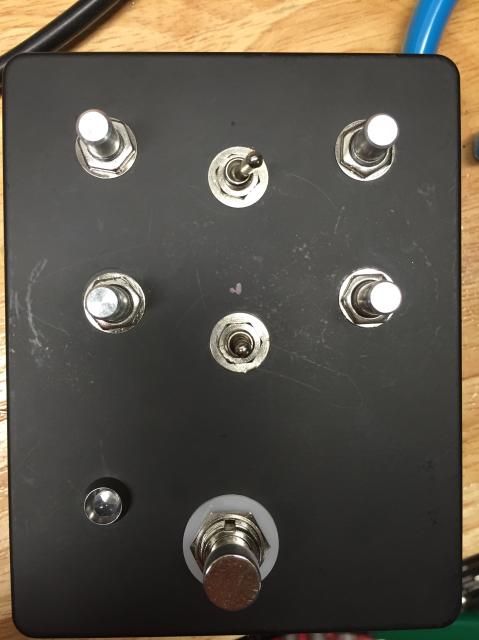
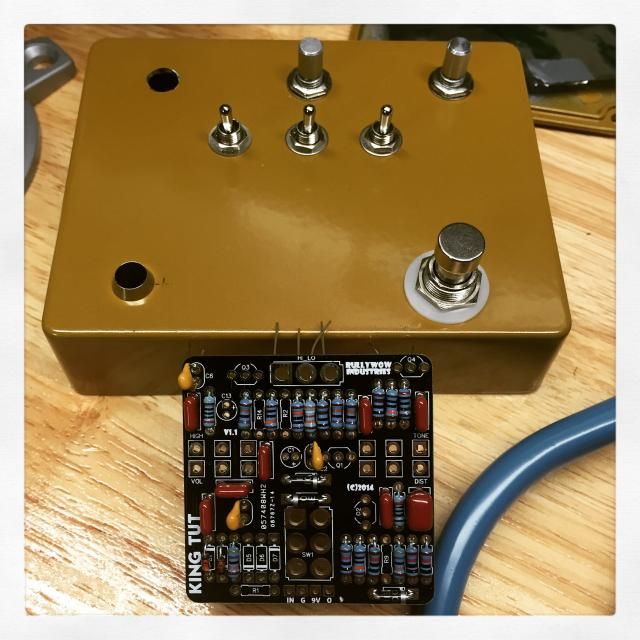
I've been on the hunt for  a fuzz that plays well with an active bass (for my bass player.)

I picked up a King Tut fuzz which is a clone of a BAT Pharoah. I got Nick from Dunwich Amps to suggest any mods, which I did. I changed one of the clipping sections from diode to LED which has less of  volume drop than the recommend diodes.

Here's some pics


Not sure what knobs I'm going to put on.


#8
Build Reports / Re: Finished up my Sunking 2 build.
February 09, 2015, 02:25:53 AM
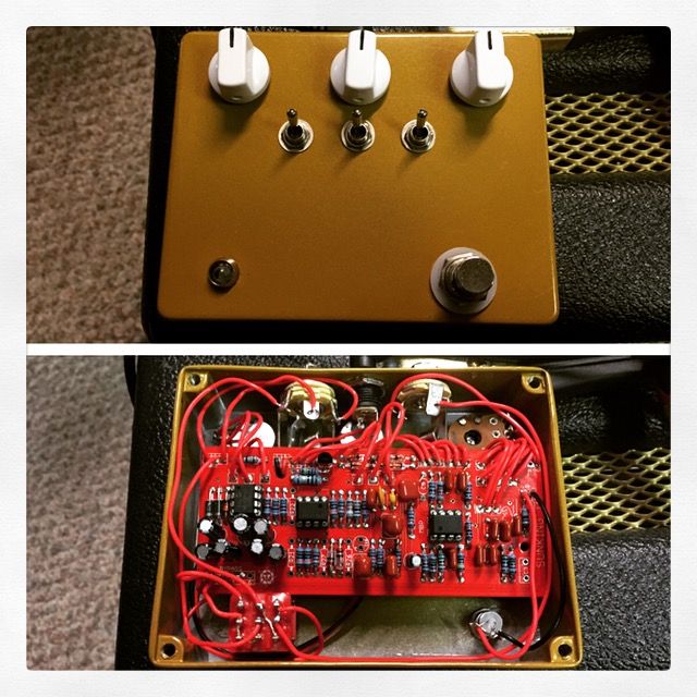
I built it to standard specs, but I did all the pots and switches not PCB mounted, and true bypass.
#9
Build Reports / Finished up my Sunking 2 build.
February 08, 2015, 11:24:40 PM
So I've been working on a Madbeans Sunking 2, which is a Klon clone... Heres a couple pics. Finished it up today. I'll take a quick video sooner or later..


And a quick vid.

http://youtu.be/AcV39yOLblQ
#10
Either way.
#11
Open Discussion / true bypass presents new issues.
January 29, 2015, 03:22:22 AM
So I recently finished up my pork barrel from madbeans, which is a Boss ce2 clone.

I plugged it in today and I've run in to a problem. I wired the Pork Barrel for true bypass and placed it as the first pedal in my fx loop, exactly where my CE2 was. Now all my delays and reverbs are after it, so it goes Pork Barrel, Dispatch Master, Echorec, Ibanez DE7 back out to the fx return.

Now when I turn on my dispatch master, I get a HUGE volume boost. The enforce does it too, but not as bad.

Is this because the CE2 is buffered and the PORK barrel is not?
#12
Quote from: blearyeyes on January 26, 2015, 04:52:32 AM
And did that fix it?

Yep! That was it. Running like a champ now!
#13
Quote from: Scruffie on January 19, 2015, 07:38:40 PM
No it should be 9V, not that 12V will hurt anything, the issue is in the LFO (TL062) it's not running for some reason.

This post lead me to check out the IC2.

I didn't solder one row of the IC socket! lol! Rookie ass shit!

I will resolder and report back!
#14
I just realized I'm running a 9v PSU with this, when it should be 12! Doh!!!! I will try it with a twelve and report back.
#15
So while my son is taking a nap, i managed to measure some voltages;

Incoming at the PCB 9v +-= 9.4v
IC1;
1-6.2
2-6.2
3-6.2
4-0.0
5-6.2
6-6.2
7-6.2
8-9.4

IC2;
1-0.6
2-4.3
3-0.7
4-0.0
5-0.3
6-0.3
7-0.7
8-9.4

IC3
1-9.2
2-4.8
3-0.0
4-4.8
5-0.6
6-7.8
7-3.6
8-0.6

IC4;
1-9.2
2-4.8
3-5.5
4-0.61
5-0.0
6-4.8
7-5.1
8-5.1

That's what I've got so far...