News:

Forum may be experiencing issues.

Main Menu
Menu

Show posts

This section allows you to view all posts made by this member. Note that you can only see posts made in areas you currently have access to.

Show posts Menu

Messages - solderfumes

#61
Build Reports / Re: First Builds - Post yours here
February 16, 2016, 03:11:45 AM
Here's mine: Tonefiend's first DIY Club project, which as I understand it is an Electra Distortion.  Pretty much from day one I was busy stuffing way too much stuff into a pedal.

IMG_1700 by dickolaswang, on Flickr

IMG_1704 by dickolaswang, on Flickr

IMG_1726 by dickolaswang, on Flickr

IMG_1727 by dickolaswang, on Flickr

IMG_1728 by dickolaswang, on Flickr
#62
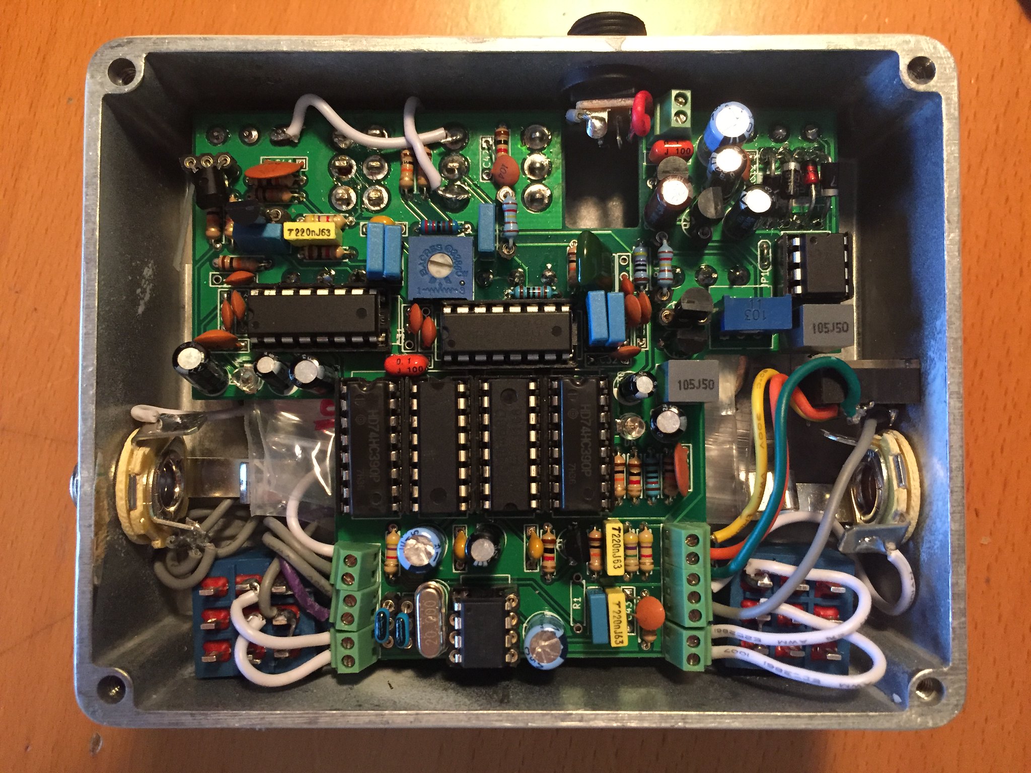
I posted about this before it was boxed, but the thread got wiped when the server problems struck.  I wanted to try my hand at Jon Patton's Hamlet Delay because his demos sound great and the circuit looked nice, simple, and elegant, but with some added bells and whistles: tap tempo, two PT2399s for extra delay, and an effects loop.  I bought a Taptation chip for the tap tempo, but when I did a little more research into how it works, I found that it isn't an ideal situation if you wanted to double up on the PT2399s.  A little more digging through forums revealed several helpful posts (particularly this one http://www.diystompboxes.com/smfforum/index.php?topic=94484.30) suggesting that a PLL would be a good way to get two PT2399s to sync without heterodyning.  There were also suggestions that this approach could be used to implement the tap tempo as well.

I then decided to finally try my hand at some Arduino programming, and after a bit of trying to get the uC to work as a tap-tempo oscillator and PLL, decided that it wasn't going to be fast enough to do both, so I programmed it to be a straight tap-tempo oscillator and turned to a CD4046 for the PLL duties.  This was fun!  I studied computer science but had never made anything that actually controls a real world machine -- closest thing I'd ever done was make two computers talk to each other, and that's kind of cheating :))

Anyway, this is what I ended up with:

IMG_2574 by dickolaswang, on Flickr

IMG_2573 by dickolaswang, on Flickr

and this is how it looks in context:

IMG_2613 by dickolaswang, on Flickr

IMG_2612 by dickolaswang, on Flickr

(My middle name is Hwa.)

I learned a lot from Rod Elliott's page too (http://sound.westhost.com/project26a.htm).  The secondary PT2399 stage is based on his Super-Simple PT2399 Delay Circuit, figure 3 on that page.  I tried to go light on the filtering on that stage, as I thought the filtering on the primary stage would handle the noise (the secondary stage actually precedes the primary one).  It almost does, but when the secondary PT2399 is engaged it definitely sounds a little gritty/distorted.  I should try a different PT2399 in that spot to see if it helps, but I can live with it, and I probably won't need the extra delay time much anyway.

I had a few issues putting it together: I fried one of the switches so it had to be replaced (which is a mean feat without desoldering braid, which I bought and promptly lost).  One of the pots was bad, too, so it had to go.  In replacing both of those things, I broke another trace on the board -- to go with the one I broke originally assembling the board -- so there are two ugly white jumpers on the finished product.  I also made a mistake on the board. I grounded pin 5 on the uC because I didn't fully understand the datasheet and thought it was an input pin.  Turns out that it can be an input if you futz around with the firmware, but by default it's a reset pin.  Next time I build it I will cut the appropriate trace, but in the meantime I lifted the pin by fashioning a 7-pin socket out of SIP sockets.

Nonetheless, it now works, and I'm still kind of blown away that I managed to get this project finished and functional!  Still gotta work on those EnviroTex and painting skills :P
#63
Nope and I assure you my layout is worse than yours.  (But it was a fun learning experience.)
#64
I've been spending the last two weeks learning to use KiCad and making a Collosalus layout (with several mods of my own).  Upon uploading to Seeed Studio, it asks whether I'd like to make the project public and I said yes, but then I realized that maybe I should have checked first whether this was kosher or not.  Is this cool?
#65
I see, that makes good sense.  Thanks!
#66
I've been looking at building an AMZ Mosfet Booster as a nice simple break from struggling with flangers, which led me to take a look at Jon's Bearhug FET Compressor.  (Why make *just* a booster if you can build a compressor and get the booster for free?)

I took a closer look at the Bearhug schematic and I have a question about D4, in the rectifier section (working from the schematic at this thread http://www.madbeanpedals.com/forum/index.php?topic=6802.0.  Is it necessary?  It just goes straight to ground.  Without it, you'd have half-wave rectification similar to that in the Orange Squeezer, but with it... what's different?
#67
I built mine switchable, including the pulldown resistor (not using the switching scheme in the build document but using a 3PDT toggle so I could leave the circuit unchanged).  There isn't much difference at all.  If you're concerned I think it would be OK to change R2 to 2M2 and that would leave you with about 1.1M input impedance.

Someone correct me if I'm wrong, but omitting R21 and R22 won't affect the output impedance.  When the pedal is on, the output shorts R22 anyway, and when the pedal is off it shorts R21.
#68
General Questions / Re: Current Lover Manual Sweep?
April 28, 2015, 06:28:25 PM
Just confirmed that the range pot can control the filter sweep on my Current Lover.
#69
Well actually I suppose I should ask: what other changes are planned for the Cave Troll?  How related is it at all to the Cave Dweller?
#70
I have them wired separately on my Kingslayer and I like to turn the clean side all the way up at all times for a little bit of clarity.
#71
Haha, well I don't want to breadboard it anymore, having seen the schematic! :)  I think I will probably end up making up a simplified version of it that incorporates the Taptation.  I'm not super interested in the modulation so I'd probably just skip that part (or use the Taptation's own modulation).  Cutting out the current mirror and the LFO makes it look not *too* painful to do on a breadboard, or even on perf (maybe).  I know there are simpler delays out there (perhaps the Sea Urchin is a better option), but I like what I've heard of the filter options on the Zero Point.

As for the Cave Dweller I would just use the mod suggested in the JMK Taptation implementation document rather than wait for the Cave Troll.
#72
OK so I see a schematic for a Cave Dweller II in the Cave Dweller build doc; is that the same as the one that's coming soon?  I'd still be really interested in perusing these proto threads.
#73
Cool, thanks!  Where are these proto threads?  I'm starting to see that a Cave Dweller might be a better starting point since I'd like to use a Taptation chip.
#74
I'm interested to try building a Zero Point SDX 2 but the boards aren't out yet.  I'd like to study the schematic beforehand because I'm a dork (and I might like to breadboard it first).  Is it possible to see the build document before the board comes out?  Even just a draft would be helpful.
#75
I built one of these (on perfboard) and I too get whine when the gain pot is all the way down.  I used two separate pots for the dual-gang pot, so it's probably not a problem on the clean side.  Does anyone have a remedy for this?