News:

Forum may be experiencing issues.

Main Menu
Menu

Show posts

This section allows you to view all posts made by this member. Note that you can only see posts made in areas you currently have access to.

Show posts Menu

Messages - BrianS

#451
Here is a link that will give you some really great info on different diodes.  Cody (Self Destroyer) and Jon (Midwayfair) are both members on here and are really smart.  Jon's diode listing covers what each diode he reviewed will sound like. Hope this will help you out. But be warned, it could start you on a journey trying to locate some of them, LOL (it did me).  Paul who runs DIYGP (link is in header above) has several on the list and he is a really great guy. 

http://music.codydeschenes.com/?p=1615
#452
The LEDs are normally much louder than the germaniums.  You can always socket your diodes and play around with them.  I don't pay that much attention to the colors and how they clip (my hearing is pretty much shot) and one circuit can sound completely different with red LEDs from another. I don't know if you have any of these sockets (link below) but if you do solder them in and then you can change out your diodes and see what sounds good to you.

As far as matching the 134's most of the time the build doc will let you know if that is necessary.

My advice again is to socket the diodes and you can experiment with what you have on hand (3mm/5mm LEDs/different colors and the multitude of silicon diodes). Sound is very subjective, as you know.  What I may think sounds great may not sound so good to you.  But with the sockets you can fool around with the clipping pretty quick if you're not liking what you hear.

http://www.taydaelectronics.com/connectors-sockets/30-pin-dip-sip-ic-sockets-adaptor-solder-type.html
 
#453
Another home run.  I really like the LED eyes. A great touch.
#454
Build Reports / Re: Green Bean Build
July 06, 2016, 11:19:13 PM
Also remember when you're using those small 9v jacks the tip is negative so it looks backwards. The first time I used one I had it wired backwards and could not figure out why I was getting -9v in till the light in my dimming brain went on.
#455
You could tie a 15 and 1 together to get your 16. I know the tepees don't look that great but it's an easy way to get what you need.
#457
I would go for a Current Lover and a couple of the others.
#458
Build Reports / Re: Green Bean
June 11, 2016, 12:23:19 PM
Looks great. The Green Bean is an awesome board. Finished mine a couple of weeks ago and I really like it.
#459
Real nice as always.
#460
Both pedals look awesomely sharp. I really like David's boards. They make such sweet sounding pedals.
#461
I made an order on May 27 and it arrived Saturday in TX using first class mail.  Paying extra for Priority and it taking the same amount of time would certainly frustrate the heck out of me. I just know it's going to take awhile to get an order from there.
#462
Build Reports / Re: Explosive Rat Clone
June 06, 2016, 04:22:56 AM
That is a really clean looking pedal. And the Bat Cat reminded me of blowing my fingers up when I was little. LOL.
#463
Build Reports / Re: Sagan Delay
June 06, 2016, 04:15:43 AM
That's one fantastic looking pedal. Great job.
#464
Got this back up just now. What an ordeal. I believe this is the first time I have troubleshot a pedal and got it working. I might have went the long way around getting it working, i.e., I basically put everything in new off board (jacks, wiring and 3pdt) and the squealing stopped but I was still getting no sound through the board.  Started probing it and my audio probe broke.  Long story short I was getting good sound all the way up to R5 and it stopped there.  Reflowed it nothing.  I replaced the resistor and put a new IC in and it fired up. Really missed this pedal this morning while playing.
#465
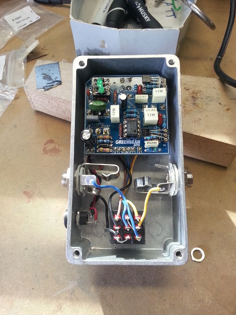
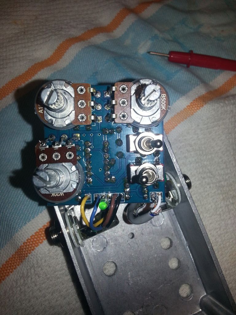
I had this working last Sunday. Took it out of the box to finish it and when I put it back in it has a horrible squealing coming out with the effect behind it.  I reflowed all the off board wiring, changed out 2 ICs and the transistors, replaced the power wire with shielded wire, grounded the output Jack lug and replaced the dc Jack. Nothing helped or changed the problem. My voltages are real close on the IC but the transistor bases are .78 and 1.12 off of the build doc. The transistors are BC 550s.  The component side picture was taken before I put the shielded wire on and the negative power wire broke off when I flipped the board to take a picture. Voltages were taken before it broke.  This is very perplexing since it was working perfectly before I took it out to finish it. Any help would be appreciated. Oh I ran this off of 3 different power supplies (battery, wall wart, and my board supply same results with all). Thanks in advance.

IC
1. 4.45
2. 4.54
3. 4.36
4. 0
5. 4.44
6. 4.45
7. 4.45
8. 8.93

Q1
C - 8.89
B - 2.80
E - 3.39

Q2
C - 8.89
B- 2.81
E - 3.40