News:

Forum may be experiencing issues.

Main Menu
Menu

Show posts

This section allows you to view all posts made by this member. Note that you can only see posts made in areas you currently have access to.

Show posts Menu

Messages - greysun

#136
Tech Help - Projects Page / Zombii question...
July 25, 2012, 02:29:21 PM
Hey guys!

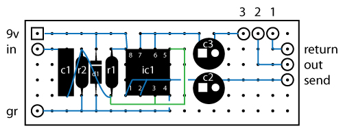
I'll be building a Zombii pedal using Perf (I know the PCB isn't made anymore - but I'd buy it if it were to come out of retirement, hehe ;D ). I'm not sure what size enclosure it goes into, but it looks like a 1590B turned sideways (it's probably slightly larger after thinking about it, but whatever).

I'm wondering why the PCB was setup in a horizontal format like that - Keep in mind that I'm a noob here - I'm thinking I could just build it so that it will fit into a 1590B enclosure like normal with the 5 knobs (4 in a square, one in the center).

I try not to assume anything, and my assumption would be that it's not a big deal - as long as the circuit works - but will it sound different if the circuit has a different layout using the same schematic? I'm not sure if I'm making sense here...

Let me know if that makes sense in any way. :P

And, as always, thanks in advance!
#137
Bump. Any ideas if this is the right direction to start work based on the schematic? :-)

Thanks again!
#138
OH - you're right - it took me a second to see that (again, my first).

I think I fixed it - here it is again:


Let me know!
#139
Hey guys - took a bit for me to get to it, but I ordered a bunch of parts and included the clean blend parts in there. I would just order the board from you JMK (always try to support when I can), but I'm building the mudbunnies this coming weekend, so not enough time to wait for the next batch of blends. :-(

I was playing with a perf board schematic to try and fit this into the mudbunny enclosure straight up - I've never done a perf diagram before, so I'm hoping this is somewhat right.

I'm trying to keep it as SLIM as possible, as it's already gonna be tight in the 1590b box, so I'm thinking I can pull this off. I was going to try to just stick it right behind the bunny board and just in front of the footswitch.

The lines that are different colors just overlap, so I needed to differentiate them. I may need to use jumpers above the fold for those.

Here's the JMK original schematic: http://www.jmkpedals.com/JMK_Pedals/DIY_Projects_files/Blend%20Pedal.pdf

Here's what I came up with:


let me know if you get a minute. Thanks again for the help - this looks very promising!
#140
I'm seeing it clearly now (i think).

With your DIY Blend schematic - and let's say I'm using the mudbunny board for this - I would go from the 3PDT switch to the IN on the blend, then go from SEND to the IN on the mudbunny, then go from OUT on the mudbunny to RETURN on the blend, then going from OUT on the blend to the 3PDT switch.

Effectively, I would put this between the switch and the mudbunny board, and I would only need a single pot to control what goes through or not, which controls how much signal gets put through the mudbunny board, and sends the remaining dry signal back to the switch to go out.

Interesting... and it sounds like it could work, and looks easier to build! I'm a fan...

Now, would sending only a little signal through the mudbunny mess with anything in there (like, would anything burn out or crap out from not having enough juice being sent through it)? I'm also assuming that both boards could share a 9v connection...
#141
ooooohhhh... okay, i think i'm picking up what you're laying down... then probably dropping it all over the place, shattering across the floor and ruining everyone's life. ;-) But I like where you're heading...

So, in practice, how would this work? Would I put a dual ganged pot before the board - one going to the board, the other going direct to output? It can't be that simple, can it?

#142
Well, you are right, and it's a good suggestion. I get my mind set on something, and sometimes i dont hear the other suggestions coming my way, so I apologize for that.

I could do it too given my current guitar setup (2 outputs to 2 amps). But would I have to split the signal on a normal guitar then to get that sound live?

I have some thinking to do about it still... I'm in the beginning stages of pedal builds, so I want to get all options possible... Keep the ideas coming.  :)
#143
well, i know it's not the same effect - like you said, that band probably uses more studio trickery than other bands (or maybe not - seems to be the norm these days, not that I'm complaining).

I just know that I got somewhere similar to that sound (and right where I wanted it to be) using my little big muff and playing with the volumes on the amp, pedal, and guitar - I'd like to keep it real from studio to live playing, so it was just a thought that I could maybe cut the volume and then boost it with another small pedal or even simple additional wiring inside the pedal itself.

You don't think so? I'm willing to give it a shot, even if I have to perf something to see...
#144
Alright, so one of my goals is to build a bunch of mudbunnies. I love the muff sound. I also wanted to use one or 2 for a light distortion - but if my little big muff tells me anything, a muff is always loud regardless of the settings.

I was listening to the song blood pressure by mutemath, and the opening riff under the lyrics is close to the sound I want. I played around with my muff (hehe) and was able to get that sound by either A) turning down my guitar, then turning up my amp, or B) turning down the muff and turning up the amp. Not ideal if I'm in the middle of a song, soooo...

So I'm trying to see if there's a way to do this in the mudbunny pedal - or even build a small outer pedal with this functionality.

Someone on another board explained that I could add a volume pot going into the pedal, and then use some kind of SuperFET boost or something - but I don't the specifics behind it, per se... and thinking about it, it might be better to have this outside the mudbunny due to the chance of blowing out an amp, hehe.

Anyone have any thoughts or tips? Thanks in advance!
#145
Alright, so... I figured it out.

Before we get into it, on another board I frequent, someone tried telling me my soldering was bad and that there was no hope unless I got better at soldering. I'll be the first to admit that it's not pretty, BUT - I have soldered things before and had a teacher that told me how to get a good solder joint, so I knew it wasn't my solder joints... Either way, this is the rest of the post (for those interested in how I got it workin)

I went through the wiring schematic and etch layout diagram a few times - everything was fine up until the transistor (the part where I was touching and it would work), which is shortly before going to output.

Had to go to google to find out how to test a transistor, figured it out with my multimeter and low and behold - the tranny was bad.

I would assume that the 1uf electrolytic cap I was using probably had something to do with this. I had popped that out earlier at the onset of my troubleshooting and used a box cap that came in the mail from a certain mr. blueshawk just this afternoon.

Then I popped the bad tranny out, used some plugs that TNBlueshawk sent along with the cap (seriously. godsend. for real), plugged it in, and it worked flawlessly. Now to clean up the wires, box it up and hope for the best!

Thanks for the help everyone!
#146
So I got home, and the connection to ground works for the bypass, but I still get issues when enabled.

I get a VERY faint sound (next to nothing, really), so I tested all connections.

I'm finding that when I touch the center lug and right lug of the transistor at the same time (if the flat side is down), I get the distortion effect.

I checked the solder joints, and it looks okay (albeit sloppy).

Could the transistor be crapped out? I have a backup, but only one.

Here are pics. I replaced a cap and it looks pretty tore up, but it is connected okay I think... The old one wouldn't come out without a fight. I even desoldered and everything. Either way, it wouldn't give me sound at the transistor if it weren't working, right?

I circled where I touched and got sound. Once I got sound, the switch and all the pots worked fine.

Pedal activated (works in bypass and LED is working)


Pedal full back. Circled the area where I'm having issues.


Pedal where transistor is - I circled the specific joints where I'm getting sound.


Top view. You can see that I'm getting power through the diodes.


Any ideas?
#147
I think you're right, I'll make a "test strip" tonight and go from there.

I did check the wiring from the switch a few times - I had everything color coordinated so I didn't mess it up, but that one I had to use permanent marker to color code and it faded, so I'll untwist it and check it again.

I didn't use board mounted pots cause I just don't trust my drilling abilities enough - bean will be disappointed with me. :( hehe.

Thanks for the tips, guys! More to come this evening...
#148
The output is not grounded, and you're right - the enclosure would probably ground it. I figured that much while I was on the way to work, actually - but that only fixes the issue when it's in bypass mode.

In order for it to work when it's enabled, I have to be touching either the switch lug itself AND the output connector, or (when switched the other way), lug 3 on the gain pot and the output connector. Would those issues be fixed if I were to box it up, as well?

I have a small tiles of brushed aluminum from an art class I took forever ago - I could drill that out to test this stuff if need be - would that ground everything, or is that not a metal that counts?

And yes, my enclosures are metal, so that should work to ground the output jack.
#149
Hey guys!

Not a grounding issue with the pedal itself, just mine.

I just started - this is my first pedal. I practiced with some other weird things (steam engine generator, guitar electronics, etc.), and now I'm diving in deep with the pedals. Anywho, here's my issue:

I made a youtube video this morning before work cause it's hard to explain - Here is the link: http://www.youtube.com/watch?v=UjKyOWyOKj4

It works in bypass mode ONLY when I touch the sleeve of the output to the ground of the input. And when enabled, it only works 2 ways:

1) if I'm touching the output cable and the mod switch, or
2) if I'm touching the gain pot and the output cable in the other switch position.

One thing of note is that I substituted an electrolytic cap in C9 because I ordered the wrong type. The positive lead is facing the FET and the negative is facing the volume, so I think that is a non-issue.

You can see that power is going through the thing - the LEDs all work, and it works when I do those things listed above. Am I missing something in the wiring schematic? Could this be related to that electrolytic sub in C9? I feel as though this is a grounding issue and I'm just missing something very obvious but very hidden at the same time.

Let me know if you guys have any advice for an idiot that doesn't know how to properly troubleshoot. ;-) Thanks in advance!
#150
I used em. I haven't connected the switches or anything yet, but was able to get the LEDs to clip a little when I mechanically connected the pots with the battery connected.

I'm going for billy from oh my gods bass sound with this one. If you're not familiar, iTunes the songs get steady, burn burn burn, the sneak, and this is the worst oater ever. He uses an old ProCo rat and said that newer ones dont have the same sound, so I don't think I'll get it exact, but somewhere in that arena is where I'd like to be. I'm using big muffs (well, mudbunnies shortly), so I hope that they work well together. Thus far, his is the only bass distortion that doesn't sound like crap live... And I've heard a lot of crappy bass distortions.