OK.. So i've been geekin my brains out and learning (and Relearning) a LOT about circuits.
Last night, I successfully fixed an ADA MP-1 that somebody screwed up trying to mod by reading the schamatic and figuring out where he/she replaced the wrong resistors and caps!! (uuugh.. that thing sounds good now!!)
ANYWAY... right now, I'm building a honey dripper and would like to do the Asymmetrical clipping mod as jimmi photon suggests..
BUT... being that i liek a bunch of switches and other garbage on my pedals.. I was thinking of adding a switch to select from the stock symmetrical 1n914s to the modified 1n34a and 1n914..
HOWEVER.. i've been doing the research on the Asymmetrical Vs Symmetrical thing....
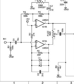
Sooooo in the below piece of the schematic for the honeydripper... I'm assuming that d1 and d2 are the clipping diodes.. correct??
Most of the blubs ive been reading through use 1 diode on one side and two diodes on the other side for the asymmetric clipping,,
BUT... Am i correct that by having diodes of different types on the positive and negative clipping sides that this is also asymmetrical clipping?? (as jimmy refers to using a 1n34a and 1n914..
so, to get assymetrical clipping you could use a 1n34a as d1 and a diffused red LED as D2 or, you could use 1 1n34a as d1 and two 1n34a in series as d2, OR use a 1n34a as d1 and a BAT41 as d2?
Last night, I successfully fixed an ADA MP-1 that somebody screwed up trying to mod by reading the schamatic and figuring out where he/she replaced the wrong resistors and caps!! (uuugh.. that thing sounds good now!!)
ANYWAY... right now, I'm building a honey dripper and would like to do the Asymmetrical clipping mod as jimmi photon suggests..
BUT... being that i liek a bunch of switches and other garbage on my pedals.. I was thinking of adding a switch to select from the stock symmetrical 1n914s to the modified 1n34a and 1n914..
HOWEVER.. i've been doing the research on the Asymmetrical Vs Symmetrical thing....
Sooooo in the below piece of the schematic for the honeydripper... I'm assuming that d1 and d2 are the clipping diodes.. correct??
Most of the blubs ive been reading through use 1 diode on one side and two diodes on the other side for the asymmetric clipping,,
BUT... Am i correct that by having diodes of different types on the positive and negative clipping sides that this is also asymmetrical clipping?? (as jimmy refers to using a 1n34a and 1n914..
so, to get assymetrical clipping you could use a 1n34a as d1 and a diffused red LED as D2 or, you could use 1 1n34a as d1 and two 1n34a in series as d2, OR use a 1n34a as d1 and a BAT41 as d2?