News:

Forum may be experiencing issues.

Main Menu
Menu

Show posts

This section allows you to view all posts made by this member. Note that you can only see posts made in areas you currently have access to.

Show posts Menu

Topics - Tdub

#1
Hello!
I'm mucking around with a circuit and would love some knowledge dropped on me.
I'm wanting to make a Dual Opamp Rat but the second stage is bugging me.

Here are my questions:
– Original Rat inverts the signal – is there a reason I shouldn't keep both IC's in a non-inverting state? I'm wanting to eventually wrap a clean blend around it so I assume I should keep both IC's the same
– Will I have enough output to just run the second ic as a buffer?
– If I don't, and want to add some gain, I'm getting confused when to send something to VR vs when to send something to ground.
– I'm also a bit confused as to when to add a VR reference at the input of the IC – some circuits use it (like a HoneyBee), and others don't (like a Timmy)

Here's my schematic
#2
I'm tinkering with a Blues Pro overdrive I have laying around and I really need to get a bit more treble/top end presence out of the tone control.

He's used an interesting high pass filter on the second part of the op amp and I'm wondering if anyone can explain a) how this works and b) how do I tweak it to get more top end out of it?
In particular the two resistors and caps together are throwing me a bit - I would understand a bit more if it was as simple as a cap in parallel with a resistor in the ic loop but I'm not sure what the combination does?

Here's a schem (note that the second opamp has its + and - round the wrong way)

#3
Just wondering how you lot are categorising/storing your parts?

#4
Build Reports / SunLion & Sunking II
May 17, 2015, 02:25:21 AM
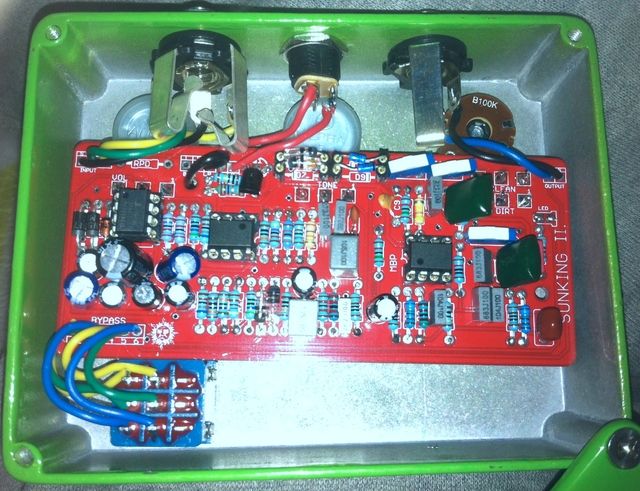
First, the Sunking. I didn't realise how little margin for error drilling a 1590BB has for the Sunking II but we managed to get it in there with a little light remedial work.

Had an issue where the 422k and 392k resistors weren't working but one that got sorted, we were away. What a great sounding circuit! I put little slider switchers on the board so I could set and forget.


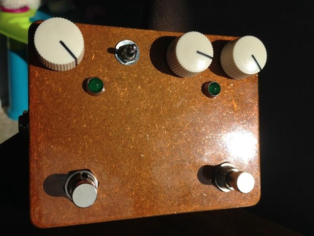
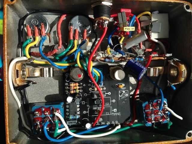
Second, the Sunlion. This ended up being a total mission to fit all the stuff in due to having a pre-drilled case that didn't put the jacks low enough. I had to remove the nice PCB mounted pots and wire them in. I had a Madbean Rangemaster board but I decided to go against using it as the new version a) wouldn't fit, b) used a BS250 that I can't source anywhere, and c) I already had the charge pump on the Mangler PCB. I used a three way on-off-on switch for the Rangemaster input and used a terminal strip layout as devised by RG Keen. It's all a whole lot less tidier that I'd like; it's a bit of a spaghetti junction but it works and it sounds good so all's well.


#5
Hi there,

I've having a problem with my build.
The overdrive only kicks in at the last 1/4 of the gain pot, through the middle it seems to drop a bit of volume and comes back up. Otherwise seems to work nicely?

I haven't been able to see a list of good voltages but I think most of mine are way off.

IC 1
1: 4.08v
2: 4.08v
3: 0.01v
4: 0.00v
5: 0.22v
6: 0.04v
7: 4.08v
8: 8.32v

IC 2
1: 4.17v
2: 0.04v
3: 0.19v
4: -6.41v
5: 0.19v
6: 0.05v
7: 4.12v
8: 11.86v

IC 3
1: 8.32v
2: 3.99v
3: 0.00v
4: -3.47v
5:-6.41v
6: 1.05v
7: 2.49v
8: 8.32v

I subsitituted a BS250 for the BC250 but that's the only thing I've changed. I did try to pull some schenangians on the 392k and 422k resistors because I didn't have any available so I put resistors together to get those values.

Any ideas?
#6
Hi Folks,

Just finished a La Vache build and I've found that it's not as loud as I expected and doesn't seem to clip at all, until you REALLY smash the input and then it has a horrible torn/gated fuzz sound that dies pretty quickly.

From memory (not at home currently) the transistor is getting Q1 3.11v Q2 .63v Q3 .53v. I've seen other voltage readings and Q1 seems like it should be around 7v (I may have my Q1 and Q3 mixed up; which ever one is meant to get the most voltage is getting half of what it should I think. I've checked all resistor values and they match up. The c4 cap is getting 9v too.

Any thoughts or help would be appreciated!