News:

Forum may be experiencing issues.

Main Menu
Menu

Show posts

This section allows you to view all posts made by this member. Note that you can only see posts made in areas you currently have access to.

Show posts Menu

Topics - catfud

#1
Build Reports / Octave fuzzarama
February 27, 2015, 09:32:28 PM
Fuzz Tonic (Madbean Wolfshirt)


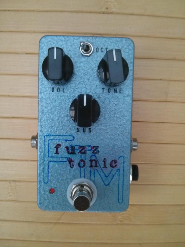
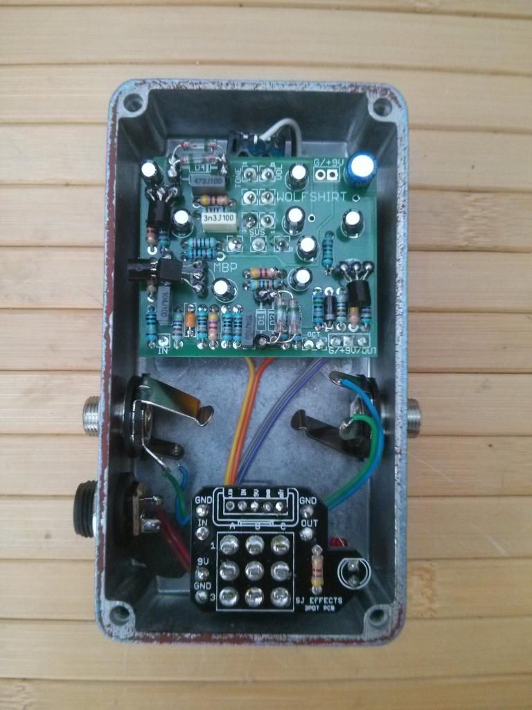
Enclosure is a Hammond 1590b, painted with Hammerite paints, and labelled with letraset , a child's stencil (borrowed), and ink stamps. The ink stamps didn't come out exactly as intended.
It sounds great, a big octave fuzz. Probably the one fuzz of the three that's capable of the most octave-y fuzz, but possibly not the most unruly of these three fuzzes.

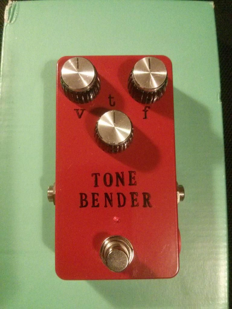
Standard Fuzz (JMK Standard Fuzz)


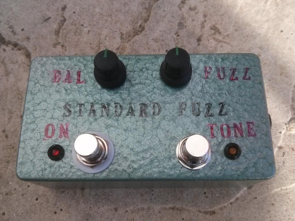
This was Jacob's PIF from from last year (Thanks Jacob, and sorry it's taken so long to get the build report up!)
I used 2N3904s for the transistors, and the resulting sound is an excellent over-the-top octave-y fuzz, with the tone boost on a DPDT stomp rather than toggle switch, and two separate LEDs.

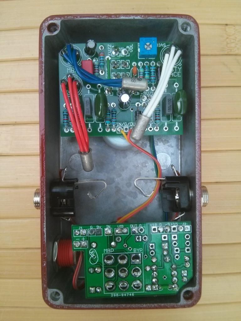
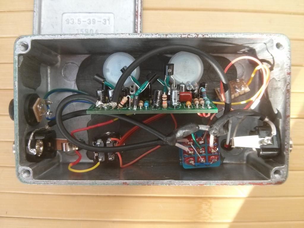
I'm not proud of the wiring, it's far from tidy, but I'm sure this isn't the intended configuration for this board in this enclosure - I was determined to make it fit this way round even if it made the rest of the build difficult.

Enclosure is a Tayda 125b that was originally intended to be used for the JMK Testing Rig, but having messed up the drilling for the testing rig I used a 1590bb instead for that, repaired this 125b enclosure using JB Weld (which is great stuff, thanks to the guys on the forum that recommended it!), painted it with Hammerite paint, and re-used it for this Standard Fuzz; pots, LEDs, and pedal are labelled with ink stamps. The patching up is visible in the gutshot.

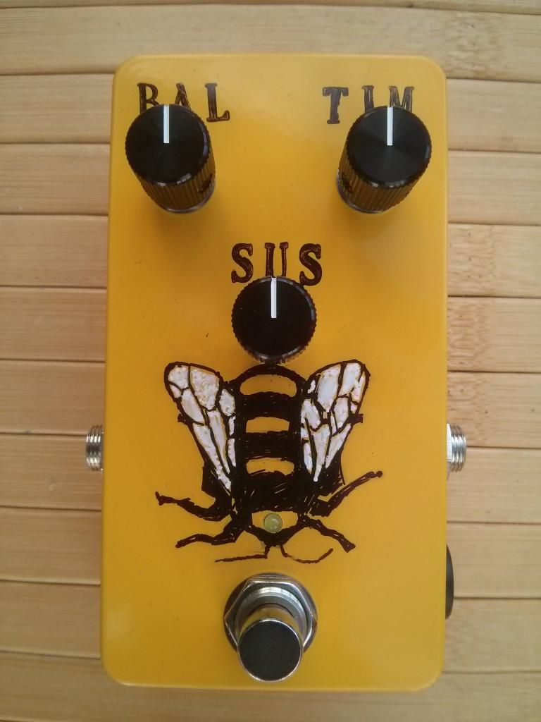
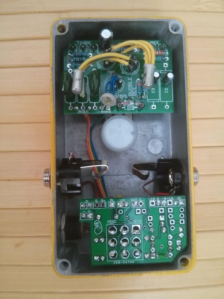
SuperFuzz (Nucleon Superfuzz)


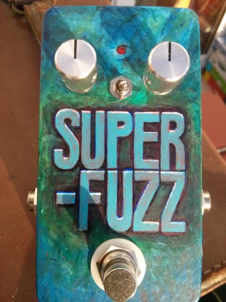
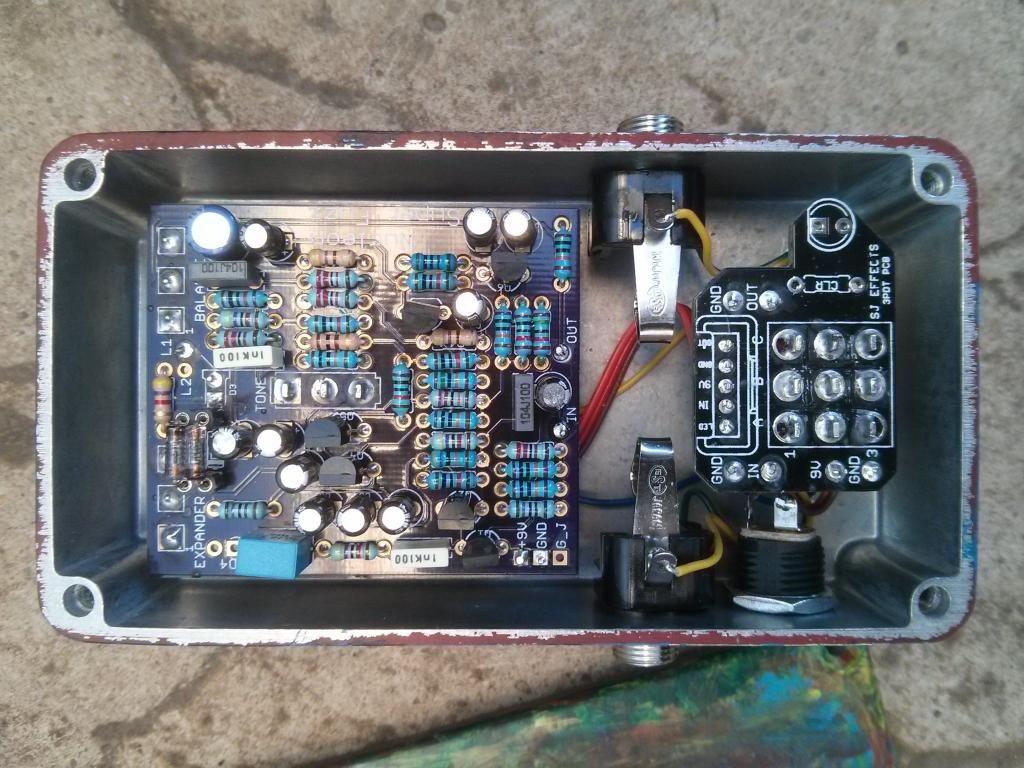
I've been wanting to build a superfuzz for some time. I used BC550s throughout (matched Q4 and Q5, which apparently accentuates the octave, with the lowest value in Q6). For diodes I tried a bunch, opted for 2 x 1n695 diodes for clipping. Last week we had some quality daddy-daughter time painting the enclosure (hammerite primer as a base with acrylic paints on top) - I did the letters, but the colour scheme was all hers. It's a wild, unruly fuzz.

Now, what happens if I chain all three together...
#2
Build Reports / Two fuzz boxen
January 03, 2015, 12:18:03 AM
Bumblebee (Madbean Bumblebee)

Using the positive ground Madbean Bumblebee board, with a Madbean 3PRR to invert the voltage supply.
I used 2 x AC128s for Q1 and Q2, and a GT108v for Q3, after trying out various combinations these sounded best to me. Loving the range of tones from the buzzaround.
The enclosure was another of the Hammond-powdercoated 1590b. Since our home is printer-free I opted for my usual manual decoration, labelling with ink stamps; I drew the bumblebee with a permanent black marker pen and decorated the wings with a white craft pen. The bee's head glows when the effect's active. The knobs are nice compact metal knobs from chromesphere's webstore.


And the Bumblebee guts:


Tone Bender (Madbean Pastyface)

The board's populated according to the Soulbender specs, with another Madbean 3PRR board to invert the voltage supply. After trying out various different transistor combinations I went with 3 x AC128s as they sounded the best to my ears. Enclosure is a Hammond-powdercoated 1590b, labelled with trusty ink stamps. Knobs are Tayda's Marshall-alikes.
Been trying to nail some early Zeppelin tones with this, and the pedal gets into the ballpark, which is nice. Also looking forward to building the Si Tonebender to compare/contrast.


And the tonebender guts:


Enjoy, and thanks for looking :)
#3
Build Reports / Caya Chorus (Small Clone)
December 31, 2014, 09:15:50 PM
My humble build of twin1965's Small Clone layout, with the depth mod and rate led. This is a really lush chorus. The enclosure, with the beautiful sparkly blue powdercoat, was from stevie1556, I'm not sure if my photo does it justice but it's a sweet paintjob (at least before I got my inks on it). Fitting the board and everything else in the 1590b-sized enclosure was a bit tight, but worked out ok. The 3pdt board is one of raulduke's. All credit to those who did the boards and powdercoating. Hope you like it  :)

And the guts:
#4
Build Reports / Flabbon (Madbean Fatpants)
October 05, 2014, 09:23:33 PM
This is the Flabbon, which is my build of the Madbean FatPants, in a 1590B, using the buffered bypass wiring. The paintjob's Hammerite, with the name stamped on with black Stazon ink. White is unforgiving when it comes to misplaced ink stamps, so there's some ghosting from where I was stamping out of line, cleaning, and re-stamping.

The pedal name is unrepresentative in respect to the sound that the FatPants delivers - the sound doesn't end up 'flabby' at all - I really like this circuit, it certainly adds weight and richness to the sound rather than making anything flabby. Besides the fat theme, 'Flabbon' is a possibly-obscure reference to a British comic strip I used to read avidly during my formative years (anyone else remember it?).

The text around the knobs and switches is letraset I bought over 20 years ago that I had squirreled away and found again recently - I checked today and to my surprise found that letraset transfer text is still sold in stationery shops.


All the parts were as per the BOM. My wiring is a bit of a mess, but I think it's improving. A few footnotes - I don't like the LED mount (Tayda one) at all so I may replace that - also, the effect of the soft switch is very subtle, almost imperceptible, but I think that's because I haven't played through the flabbon with a particularly bright guitar.


Thanks for looking!
#5
Tech Help - Projects Page / Filling misdrilled holes
August 01, 2014, 02:46:31 PM
I've read that some people use JB Weld to fill holes in enclosures; for those that do, is it the original epoxy adhesive that should be used, e.g. this, or one of the more exotic JB Weld products?

(because I misdrill my enclosures more often than I care to admit and want to fix them)

Any pointers would be much appreciated :-)
#6
Sorry if this has been covered in previous threads (my searches drew a blank) but is there a strong reason not to use solid-core cable when wiring up pedals? Are they more prone to breakage than stranded?
#7
General Questions / Dual-gang pot search
January 07, 2014, 10:28:43 PM
I'm trying to track down a supplier of Alpha Dual-Gang 16mm right-angled PC Mount pots in Europe, but my google-fu is made of fail today. I could get the non-right-angled variety, but I'd rather the right-angled sort if I can find them.

Would anyone be so kind as to point me in the direction of a vendor that stocks these please?
#8
Open Discussion / Drill Templates
November 02, 2013, 12:03:25 AM
I've got a drill plan on graph paper for an enclosure I'm working on from scratch, but want to transfer it to a drawing program. What drawing package do you recommend for drill templates?
#9
How Do I? Beginner's Paradise. / Can flux cause shorts?
October 25, 2013, 06:12:38 PM
Probably a really silly question, but can excess flux cause a short circuit? Just trying to figure out the cause of a temporary short circuit...
#10
Tech Help - Projects Page / Road Rage question
October 25, 2013, 12:27:17 PM
I'm wondering whether I'm being a total noob and have been misunderstanding the Road Rage - I've been trying to use it to switch between different voltages, but have been running into problems.

Is the Road Rage intended to supply a single voltage only - i.e. to be partly populated according to whether you want -9 *or* 15 *or* 18 volts from a single board? I've fully populated a Road Rage with the intention of switching between the different voltages on-the-fly, expecting all voltages to be available from the respective pads, but the pesky voltage isn't behaving the way I was expecting/hoping.

Feel free to slap me with a metaphorical wet fish if I've got the wrong end of the stick...
#11
General Questions / PCB mount pots in uk?
October 12, 2013, 11:36:13 AM
So far I've been wiring up pots that could be mounted on a vertical PCB, but I would like to find a source, preferably in the UK, for the pots that will mount on a horizontal PCB - I mean the ones with right-angled pins. I haven't found a source yet, does anyone know of one? Or are these only available internationally?

Thanks for any feedback!
#12
I suspect this may be a silly question (sorry!), but can I use the various different power outputs from a Road Rage simultaneously to feed different circuits with differing power supply needs?

For instance, to feed a Ge fuzz the -9v output while simultaneously feeding a headphone amp the +9v output, with everything using the same ground...
#13
General Questions / Big Muff variant question
September 28, 2013, 07:22:09 PM
I've tried a fair bit of web searching but my google-fu is weak today. Does anyone know of a site that has a full set of comparative sound samples of the different variants of the big muff? I've got a mudbunny PCB to play with, and want to decide on one to build.
#14
I couldn't find a 7815T from local parts suppliers at the time I was buying parts for populating some Road Rage boards, and I bought some BA17815T instead (TO220 power regulator). It looks to have the same specs, but I'm not totally sure, and since I don't want to fry my build unnecessarily I wanted to ask "has anyone used these for the Road Rage, or can anyone advise on whether it's sufficiently equivalent?"

I was also surprised to find that both the heat sink and the body of the part is encased in plastic (I had expected the heat sink to be bare metal). Is that normal for a TO220 power regulator?

Any advice is much appreciated, and sorry for the noob question, I've been getting confused over datasheet terminology.
#15
I've been considering building multiple independent switchable circuits in a test rig, some to run concurrently, and I want to see whether I could run them all off the same +9v supply. Thinking of, for example, a sound generator, a headphone amp, a voltage inverter, and a charge pump all in the same box with various switches and pots to switch between them, and in some cases control their currently active parameters.

Two questions about this:

1. Is this practical from a power POV?

2. If it is, I imagine I would need to be sure that the current draw would be within the capabilities of the power supply, so how would I go about measuring the current draw of each circuit (with my multimeter)?
#16
How Do I? Beginner's Paradise. / Knob height
August 28, 2013, 09:20:17 PM
After mounting pots on the enclosure and adding a knob I find the knob stands proud of the enclosure - I'd prefer the base of the knob to be flush with the enclosure if possible, and some options I've been musing are to either use a hacksaw to remove the top part of the pot shaft (which would probably lead to unevenness between different pots on the same pedal) or to pad out the underside with 1 or more washers (which will lose internal enclosure space).

How do others get the base of the knob close to the top of the enclosure, or is a gap considered inevitable? I've not seen any from my usual supplier, but is it perhaps possible to buy pots with shorter shafts ?
#17
Tech Help - Projects Page / Mangler issues in testing
August 22, 2013, 10:48:08 PM
This isn't my first build, but while the previous one went swimmingly (rangemaster) the mangler is causing more issues, meaning I'm having to seek the collected wisdom here... thanks for reading...

Project Name: Mangler

General Description of the problem:

No signal being passed through the circuit apparently, and odd biasing readings

Steps I've already taken:

The first thing I tried was to bias the board - my multimeter on the test point shows about 9v which isn't right...
Checked wiring, part values, and orientation (although the positive ground is a tad confusing I think orientation is ok)
Checked my soldering (no bridges or problem joints s far as I can tell)
Tried putting several different pairs of transistors in the sockets, same results
Tested continuity with a multimeter as far as possible using the schematic, no problems there
Done as much testing of on-board components as possible considering they're soldered in place (though my crappy DMM doesn't stretch to capacitor testing)
Replaced all caps and the diode
Tested the test rig, in case that's a problem, using another positive ground effect (rangemaster), and that's working ok.
Tried playing the guitar with everything connected - direct from guitar to amp works fine but no signal with the effect in-between.
Tested Battery (which is fine)

Any substitutions:

None, all component values are as listed in the Mangler PDF

Voltage readings:

    Q1    Q2
E   0     0.01 
B   0.16  0.01
C   0.01  8.98

The 20k trimpot doesn't reduce the voltage much to Q2, I think I'd need a higher value pot for that if there's not some other problem. But I'm guessing the real problem is elsewhere, and with luck not between the keyboard and the chair.

Does anything leap out as being an obvious problem to anyone? I keep coming back to it and drawing a blank - I just can't see what the problem is. Any pointers from you more experienced folks would be much appreciated. I've included some links to pics of the board.