News:

Forum may be experiencing issues.

Main Menu
Menu

Show posts

This section allows you to view all posts made by this member. Note that you can only see posts made in areas you currently have access to.

Show posts Menu

Topics - midwayfair

#41
The model I used (a Canon) isn't really made any more, either. My dad gave it to me for Christmas several years ago because it sounded better than the newer models, even the nicer camcorder he had. I don't like doing iPod videos, which is really my only other option at this point, and replacing it with something proper isn't really in the cards. And I have previously gotten supremely frustrated trying to do video editing of any sort on my minimac or I wouldn't care what was capturing the footage as long as I could mic the cabinet.

It was not a good camera. I never had the power adapter for it, so I had about 30 minutes of battery life at any given point. It used a USB card and the biggest one I had that worked in it was only 8GB, so I had exactly 13 minutes and 47 seconds available to get a demo right. And of course it compressed the sound and even did weird zoomy things when the auto focus got confused. These limitations really informed how I decided to do demos, which was more of a review of the circuit and functions and what the pedal was capable of rather than a demo of how it exactly sounded.

I'm kind of thinking this might mean the end of my video demos. :(

I'm not looking for sympathy, but given the time span since I last posted a video, I thought some explanation might be in order, even with the sparseness of my build output the last year while I focused on studio stuff.
#42
My friend Matt Pless wants to do a European tour. Most of his gigs here are house shows, so he's looking for small venues and folk venues, places where lyrics matter to people.

I don't use the term "great lyricist" lightly. Matt's one of the cleverest writers I've ever met. I usually describe him as Billy Joe Armstrong doing Dylan but he's very much become his own thing.

https://mattpless.bandcamp.com/track/the-crayon-song

Any help is appreciated.
#43
Build Reports / My May-Dec 2015 builds wrap-up
January 20, 2016, 04:24:58 PM
Usually my Madbean reports are more comprehensive than the summaries I post elsewhere, but I was a bit more lazy the last few months.

----------------


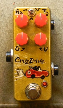
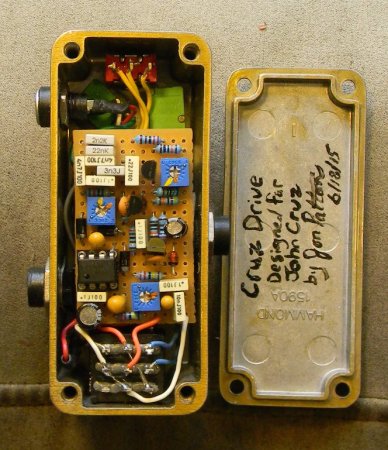
This started out as an adaption of the Tube Driver for a 1590A, but turned into something more like "in the spirit of" instead of a direct adaption, but I reeeaaaally like how it came out overall, halfway between a booster and an overdrive but still capable of some pretty gainy sounds. The project thread is gone, probably the only major thing I lost in the forum crash -- I didn't make a Google Doc for it, but Thomas retained a pretty good amount of the text in the PCB documentation: http://diy.thcustom.com/jon-pattons-cruz-driver/

And here's a quick demo I recorded as a warmup before going out to play: https://dl.dropboxusercontent.com/u/9878279/Test%20recordings/Cruz%20Drive%20demo.mp3

He didn't have any instructions for the art beyond having labels for the controls, so I named the build after him and put a red roadster on it. vroom vroom!


QuoteThis was a fun challenge, and it came together pretty quickly once we identified what would work well with his amp at home (a Bruno S100, holy crap) and on a big Fender. At home he just wants a "more" button, so I had to make sure there was a flat dirty boost in here somewhere.

I replaced the op amp buffer + inverting drive stage with a MOSFET booster, and replaced the tube stages with with FETs in the normal manner. Note that the design inverts phase, which the original did, too.

I moved the tone controls to put it before the last gain stage because otherwise it was just insanity on the gain levels. It's already pretty nuts even with all the cuts in front of each stage, but this gives a lot more control over the overall clipping. The tone control and switch are really what make this cool. (Thanks to Cody and Thomas for tossing around some ideas, even if I ultimately went with something different.) Really I'm just repurposing once again the tone control from my Sakura amp, but everything worked out just right for me to get a third mode out of this one and to have a usable bass control.

1) The bass control just shaves off some low frequencies below about 400Hz. It's is a shelf filter, so the bass isn't gone, just deemphasized, and at 5:00 the cutoff is at 18Hz.

2) Treble/Tone control: This is based on a version of the Big Muff tone control, with the resistor to ground for the low-pass removed. A lot can be done to radically alter the behavior of the tone control just by varying C9, so that's what the switch does. R8 is a small resistor (I picked 2.2K) to limit the ultimate range of the tone control so that it doesn't turn into a full low-pass filter, but it can be omitted for some very very dark settings in the scoop mode. I just don't like tone controls that bottom out.

Three modes:

a) Mode 1 flipped to one side: Flat treble at ~3:00 on the knob, at 5:00 a VERY tiny boost in the treble above 700Hz, and CCW cuts the treble at that same frequency, like a see-saw. With both tone controls down, it'll form a mid hump right around the middle of a Fender amp. (If I were to leave off the switch, this is what I would use as the stock mode.)

b) Mode 2 in the center: At ~3:00, the mids are boosted by about 3dB centered ~1KHz (bass and treble are flat). There's again a slight treble boost at full. CCW, the treble gets cut at 2KHz, so it's milder than mode 1, for just shaving off the harsher harmonics created by the distortion. This mode was a freebee on the layout by adding one capacitor, so I saw no reason to omit it. It's not as dramatic as the other modes, but it will usually sound flatter when there's a lot of distortion present.

c) Mode 3 (flipped the other way) has a mid scoop at ~250Hz for added clarity (this is the "mud" frequency for guitars, so it's a good frequency to cut). CCW, the treble is cut very deeply, which allows for bass boost with the bass at full and the tone turned down, or a treble boost with the tone up and the bass down. But with the treble and bass at about 9:00, it's back to a nearly flat response but with the gain cut a lot, for some "mostly clean" boost settings.
---------------------

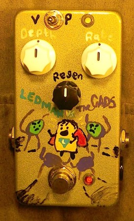
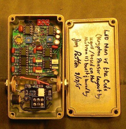
LEDman vs. The Cads -- kgull's Mutron II PCB.


Before I get into what a mess I made of things with this build: Major kudos to Kgull for an amazing layout.

I had one problem after another with this build. I fired it up the first time and my rate indicator blinked but not the one for the effect. Scratch my head, poke everywhere, remove and replace some chips ... woops put a TL in backward and popped an LT1054. Crap. Toss it. Poke around some more, eventually get the bright idea to remove the LED and test it ... oh, it's a dead LED. Toss it.

Replace the LED. Something not working now. What the heck? Oh crap, I mixed up the leads on the power and ground when I plugged them back into the breadboard. Popped another 1054. Replaced ... oh crap, I had popped the Zener a minute ago, didn't I? Replaced it.

Everything's finally working in the LFO. Plug in all the audio chips ...... only dry sound, no phasing. Well that's weird. Do some audio probing, figure out that one of the chips must be dead. Unfortunately, I'm out of TL072s, and I only have a couple TL062s. Replace the chips one by one until I get audio at the phaser section ...

Put one in backwards. Smoke from the 1054.

ARG. Replaced.

Go to box the thing up, and here's where it gets really stupid:

(a) I wanted to use up this box, but I had already drilled it. It's got an extra hole. Hey, I'll just add a dry lift for a vibrato mode. More on that in a minute. Annnnd my rate LED won't reach.

So I desolder the rate LED, add legs ... resolder and ...

What the? Now the rate LED isn't blinking. I pull it and test it ... still works. Look all over the board. Eventually (not even lying -- like a half hour to find this) I find the lifted trace, after scraping away a bunch of solder mask and being completely unable to find the trace to pin 2. Resolder ... still not working. Huh. Somehow managed to blow the LED WHILE TESTING IT. Replaced. Finally everything's working again.

(b) The Lumin board is the only optical bypass that will fit. And it's masked on both sides ... so of COURSE I put it on the switch upside down. And I don't figure this out until after I had wired everything backwards. But I get everything soldered up, test the bypass, everything works.

Oh, I forgot ... I wanted polarity protection. Desolder the power wire and install a 5817 between the jack and the switch PCB. You might guess where this is going ...

Plug in ... nothing. Not even the bypass LED. How is that possible. 0v on all the power pins. What the hell?

Eventually -- again, not even joking, at least a half hour -- I figure out that I'm getting 9V at the input on the board because my probe is hitting the lead of the diode itself, and I see that I lifted the pad for the power trace on the Lumin. Desolder the diode, use a new one and go to the other side of the switch (thanks for putting two pads, Rej & Jason!).

Finally ready to go.

With that much troubleshooting defeated, I felt a bit like a superhero, so I went with a comic book theme (Baltimore Comicon is next weekend, too, though I'm not going).

If you don't get the pun in the name of the pedal, most photocells use Cadmium Sulfide, abbreviated as "CdS." So, the enemies are the cads, crowding around LEDman.

As for how it sounds, it's different enough from the other phasers I've made that I think it's worth a build. (I prefer the Stage Fright overall for intense phase, I think.)

I used Smallbear's 9203 photocells. These have a high dark resistance; I found that to get the most out of this pedal, having the LED go darker gave a more pleasing sweep on the treble side of things. I actually used a 2K trim for the LED limit, and it's dialed almost all the way up; I also have the 10K balancing trim past noon. The sweep sounds a little lopsided no matter what, but this gives a really wide sweep and seems to get the most out of the circuit.

My one mod was the dry path lift, to create a pitch vibrato effect. I don't think this was worth it. It's a subtle difference with the Regen fully CCW and sounds kind of interesting -- but it's basically unnoticable at higher regen settings except that a very small amount of extra bass comes back in when in phaser mode. It's possible that there was a better way to implement the mod and maybe lifting the Regen as well would have helped make the Vibe setting more noticeable, but I couldn't do that with only a SPDT, and I couldn't fit a two pole switch.

---------------

Verified the new Cardinal V2 PCB.

It's been a long road, but it's finally here! I probably spent more time overall on this design than anything else, and the new project has been improved in pretty much every way from V1. Josh's new layout is pretty killer, too. The new PCB is slightly smaller than V1, so now it will fit with the Optotron for those who want to use optical bypass (which I highly recommend with FET-input effects). The pots and switch are all board-mounted now as well.


Important Note: there was a rendering error due to an incompatible part between my Eagle library and Josh's on the prototype PCBs. The final version of the PCB has the Vactrols rendered properly and they will be installed with the writing up. (If you were wondering about the solder burns on one of my caps and one of the vactrols, that's the explanation ...)

You'll also notice that, klutz that I am, I drilled the blinking LED on the wrong side of the enclosure. Derp. Don't be like me, kids!

Otherwise, it came together very quickly (despite the need to match a couple components, it's way easier to dial in the effect to be perfect now). It's my standard art, which everyone is probably sick of at this point, though I did have some fun with graphic labels on the knobs instead of werds.

There are some extra spots on the PCB for optional components, including a +6dB boost for the first stage and optional miller caps for the second stage, which I leave off on my builds.

Here's the demo:


---------------

A Hamlet delay with an oscillation switch and the tone trim external -- part of a trade with the next pedal for a pearl drum kit that needed some work. He insisted on a battery even though I explained that the pedal would easily drain one in a few hours. The last of the black PCBs. I'll miss them!


A plain-Jane Orphan Fuzz. He wanted mostly unadorned enclosures, but I did sneak in some silver strings on the "O" to make it look a little like a harp ...


Another Hamlet, for local guitarist Quinton "Q" Randall. That's him inside the Q. :)


---------------------------

Built for a (repeat!) customer. I took the fuzz and bias controls from the Rust Bunny, changed the tone control to affect the bass only (from the Vox's original massive bass cut at 1KHz down to 144Hz with the bass all the way up), and built it up on perfboard with a pair of germanium transistors (a Russian MP38A hfe ~75 in Q1 and a US 2N388 [I think that was the part number] ~52 in Q2) with gain buckets similar to reported values from some vintage units. The relatively high capacitance of the Russian transistor (which is part of what makes them sound so good) helps smooth things out for most of the distortion to keep it from getting way too harsh, and the relatively low capacitance of the 2N388 kept it sounding very edgy. Although the circuit looks like a Fuzz Face, it sounds different and doesn't clean up as fast with the guitar volume, which is pretty typical of having the gain buckets "backward" -- if I were to swap the positions of the transistor pair it would react just like a Fuzz Face, but multiple posts I found about the Vox TB confirmed that the second transistor was lower gain than Q1. It also isn't quite as dirty as a fuzz face overall.

I made it on perfboard because I would have been jumpering half the component slots on the Bunny's PCB, so this just seemed tidier.

I really like how it turned out and I kinda want to make myself one.

Another customer build:


Tetragrammaton. A Snow Day and Cappuccino (percollator clone with extras) 2-in-1 for a customer in North Carolina. He named it and provided some usual bits of artwork he wanted in there.

I was particularly happy with the way the sky came out -- I did layers and then used thinner to get the swirl effect. Diodes for the Cappuccino are 1n695 (odd) and OA126 again, but there's also a diode lift. The Snow Day was build on the Madbean board with some compromises between my original and Brian's improvements to the circuit.

I accidentally cut the wires a little short on the Snow Day's power, and I couldn't get the wire back through the soldered hole, so it looks a little messy in the corner, and I had to flip the bypass PCB upside down to get the LED in the middle, but otherwise a straighforward build. The Snow Day board was a leetle bigger than I expected, so I had to do "portrait" instead of the "landscape" orientation I usually use for 1590BB 2-in-1s.

This is a pretty killer combination. He plays garage rock type stuff so I think he's going to really like the OA126 setting on the Perc stacked into the no comp setting on the Snow Day.

-----------


Fallstaff with a beard for a customer. Very slight tweaks to the original frequency cutoffs (I updated the build document), and a black glass CV7003 that I've been holding onto for a while.
#44
The EM drive -- no, not the underengineered boost pedal -- might actually work. Or rather, it actually did work inside a vacuum.

http://io9.com/new-test-suggests-nasas-impossible-em-drive-will-work-1701188933

It works by bouncing microwaves off a surface and generating momentum without being subject to the laws of conservation of momentum. It's frigging magic.

It's not warp drive but I'll take it for now, if only because it shows that pesky physical limitations might not be such a worry after all.
#45
Some background: A guy named Freddie Gray with a long rap sheet was arrested and died in the back of a police van. Although there has been no released report on how he died, there are rumors that he managed to break his own neck by banging his head against the side of the van, in which case he probably wasn't properly restrained. Anyway.

Some high schoolers in NW Baltimore staged a walk out today, with some people apparently itching for a fight; the police showed up in full riot gear with live bullets, tear gas (which is illegal to use in warfare, but not on your own civilians in the U.S.), and pepper spray.

They ordered the kids to disperse ... except that they had shut down public transportation in the area. For some context, all Baltimore high schools are magnet schools, which means most of the students don't live anywhere near their school but bus in; and there are no yellow school busses for high schoolers. So there was literally no way for most of them to get home.

Some rocks were thrown at police cars. The police gassed them and sprayed them with pepper spray. The exact timeline is unclear.

Then the situation continued to escalate. Guns were pointed at protestors. (Remember, they're high schoolers.) More rocks were thrown. A police officer was seriously injured. Twitter gets ugly and, as it is wont to do, incredibly, unbelievably racist. The Police twitter is characteristically tone deaf.

Some cop cars got burned. Then at least one cop van. So far as I can tell, a large part of the property damage is confined to police vehicles, at least for the pictures on my twitter, but I expect a lot of windows will get broken, certainly more than the comparatively minor damage done on Sunday.

Some neighborhood residents are turning out to form a human shield. Some part of the protest is a few blocks away from downtown.

All of this is very far away from where I live. My own little protest is to go downtown, play some music, and hang out with my racially and culturally diverse group of friends at the Teavolve open mic.

From my vantage point, the problems with the Fergusson riots were not learned by the Baltimore Police Department. The police were the ones accused by the public of wrong doing but are still the ones tasked with keeping the peace. It's the fox guarding the henhouse. I am hoping the National Guard gets called in soon so there can be a neutral party watching over the protests. Because right now, Deescalation doesn't seem to be on anyone's agenda.

I'm hoping that anyone who threw a rock feels ashamed tomorrow. But I also hope that whoever decided to gas and mace a bunch of high school students also wakes up ashamed of themselves. There's really nothing good to say about any of this today.

That's all.
#46
I'm playing in Portland OR at the Waypost (3120 N. Williams Ave) on May 7 with Jake Kelly and Barry Brasseau. I only know a couple people out there and I'd like to help make it a good show for the locals. If you know anyone who likes folk music, please send them our way.
#47
Build Reports / "Black Hole" Shoot the Moon mini
April 26, 2015, 09:39:17 PM


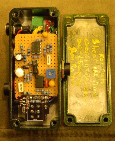
A customer up in Boston wanted a tremolo that could do stutter and softer wave forms and it needed to fit in a 1590A. He also wanted the rate knob as big as possible, so that meant I had to fiddle with the layout a bit to exclude the volume and make the waveform control a switch!

He plays bass clarinet, so I hope I get to hear something he creates using this!

I was so happy with the art that this one was a wrench to let go. I used "Midnight Rain" from PPP as the base powder coat -- it looks black but has a green sheen when the light hits it just right, and it also has some sparkle to it. I didn't want to use a flat black because I thought it would lessen the impact of the big black knob that makes up the black hole itself. Since every black hole needs something to feed on (or else you wouldn't be able to see it), I used the stuff sticking out of the pedals, and the LEDs obviously made the most sense. The colors start out "cold" (except for some silver around the edges to add some separation from the background) in actual heat terms and get brighter as you go toward the center of the accretion disc. There is also a white and silver background to make it look more like actual light. It's hard to photograph the metallic paints properly.

The Hawking radiation (that column shooting out from the center) was done with white and metallic blue.

I then used some paint thinner to smear the colors together and get some dissipation at the edges.
#48
I need to know the resistance from cathode to cathode on two 1N4007 diodes (or similar) with their anodes connected together. I know it's well over 10M and so my multimeter won't measure it. I'm hoping it's similar or higher than the 300M across FET junctions.
#49
I went back to a recording I did in December with the intention of just adding backing vocals, which I didn't really have any proper ideas for when I first did the track. Heard a few things that weren't quite there for me in lead vocals, so I started redoing them.

I ended up with 149 new takes of the lead vocal by the end of the day. And you know what? Except for about half a line and a half second here and there, it almost nails what was in my head in every way: timbre, pitch, and delivery. I don't think I've ever managed that with vocals except once or twice by accident.

I know it seems obvious that if you do something lots and lots of times it'll get better, but sometimes it's hard to remember what "a lot" is (usually, if I hit 20 takes on any line for a song I already know the melody to, I think I've gone overboard), and visualize just how much better something can get, especially at those times where you aren't even sure you're capable of doing something or, worse, aren't sure what you're looking for that's making it unsatisfactory. I had a string of takes in the middle that weren't improvements, but rather than go back to an earlier take, I kept doing things until I heard the "right" take on one verse, then went back and polished up the previous take. After about 8 hours, I kind of wished I had the time to get up the next day and do it all over again on a different song. (I'm reminded that Springsteen spent entire weeks in the studio for the Born to Run sessions doing nothing but vocal takes all day, one after the other.)

ah well, back to my day job now ...
#50
Spotted on TGP today:

Quotebut I've been looking to get a really warm and bright overdrive to add to my board

On DIYSB the other day (different person):

QuoteI meant something clear, warm and bright

When I told the DIYSB guy that he was, to the best of my knowledge, asking for a circuit to do two polar opposites at the same time (he also wanted a "completely clean" tube preamp circuit that adds harmonics and sustain ... but isn't a compressor and didn't EQ the signal), he said:

Quoteyes, you can have warm and bright sound. The equilibrium point between these two is a matter of aesthetics.

Anyway, no offence, any musician in here understands what I mean and looking for.

So since I'm clearly not a musician because I can't frigging understand this, what the hell definition of "warm" are people using that encompasses "bright"?
#51
Open Discussion / Need opinions on ribbon mics
April 01, 2015, 04:31:30 PM
I'm looking at several ribbon mics. I'm specifically looking for something to pair with my Sennheiser MK4 when dual micing.

My only references are a Fathead -- which I think is too dark -- and a Royer 121, which I can neither afford nor justify buying for making demos. The other mics I have around that get the most use are a 609 and an AT pencil condenser that's also quite dark but also doesn't really have good detail even in the low end. I'm primarily looking for a ribbon to take over for that one.

This is the stuff I'm looking at:
Fathead -- yeah, I already said it's too dark, but the basic version is only $120, which is hard to beat, and it's possible that a transformer swap would get me where I want to be.

Naddy active tube or FET ribbon -- I would expect this to be brighter than their passive microphones, not just because of the active circuitry but because the ribbon is only 2mm as opposed to the 6mm listed in their spec sheets. All their ribbons have gotten decent reviews on Gearslutz, but I really need to know how they sound compared to the mics I've actually heard. There's another reason I'm leaning toward this, though (see below).

RM-5 kit: http://www.diyaudiocomponents.com/diy-kit-manuals-rm-5-ribbon-mic. Because If I can build it, why the heck not. My impression of this, and based on some clips, is that it's a little dark. I'm not sure that's where I want to be.

Austin DIY kit: This one sounds brighter to me than the RM-5, but it's also more expensive by almost $100; again, though, this could be a transformer issue, and I can get the RM-5 without the transformer if I can figure out the ideal part to get for that.

I mentioned that there was a reason I was leaning toward the tube mic. It's not so much that I'm like "ooooh tube!" (though I will admit that gets the ole saliva flowin'), but rather that my interface only has two buttons for phantom power, and when I'm using all four inputs, I'll usually end up with 3 active mics, and I'm worried about damaging a passive ribbon mic. Apparently dynamic mics don't have this problem, but I've read about people blowing up a ribbon. Does anyone know anything about that?

Please let me know if there are other mics I should be looking at. If I get the right ribbon, I'll just be one tube condenser mic short of my ideal home recording mic cabinet.
#52


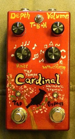
This is my tap tempo build of the new Cardinal -- and it's mine, ALL MINE. I still need to build another analog one (just got more photocells from Smallbear) for the demo, but I'll get a demo of this one recorded sooner rather than later.

As much as I improved on the analog version of the Cardinal, this got the biggest improvements to my previous tap tempo harmonic tremolo layout. Despite the small size (made for a 125B with any orientation or jack location), I managed to fit the optical bypass on-board. It uses a simple NPN/PNP complementary pair provide out of phase PWM signals. Also, some fellow forumites (especially Rob) helped establish that tying the PWM buffers to +9V works, which allowed a much higher depth range compared with the standard setup from Taylor's Tap Tempo Tremolo, so just like the analog version, the square wave is REALLY square (even without distorting the waveform). I'll get deeper into the technical bits in the build thread for the new version of the Cardinal.

When I made the first tap tempo version of the Cardinal (which this will replace on my main board), I used the concentric pots because they helped save room on the enclosure. The neat thing with using them this time is that it makes the tap tempo version look like the analog version.

Smart cookies will notice that I forgot to paint a 16th note. Oh well. :(

The art references the Sakura amp. Instead of cherry blossoms this weekend, we got snow, though. Oh well.

There were some small issues boxing it up. The main one is that I designed the PCB to allow a dual LED with a common anode (which is a rare part) and getting that into a bezel was really really problematic ... I ended up snipping/filing down the legs until I could put some heat shrink on the whole LED and fit it through the bezel. Also, since there's no board mounted pots (I wouldn't have been able to fit them on the PCB), the PCB is held in place with a combination of some solid wire, double sided foam tape, and the tap switch itself.


Here's my weener! Finally! Joe Gagan was super incredibly nice and sent me one of his Smooth pots and a replacement rack to use after I had some technical difficulties (manufacturing error combined with some weirdness in this wah enclosure), and I'm happy to report that it's hands-down the best sweep I've gotten to play with in a wah. It has more aspects of the Vox (which I prefer to a crybaby) without being way too spread out like an ICAR, and the sweep is HUGE. I got to about 2 gear teeth away from the entire sweep of the wah pot, whereas most wahs only get about 2/3 (if that).

I used one of the small 4-position rotaries to add a "super double chubby" mode (it's the small + large caps from the Weener's 3-position). I used a 2N5485 for the boost to get less distortion; I only wanted the boost to add a tiny bump, without being entirely clean.

I also really like the sound of the Yellow Fasel, though I didn't try another inductor in this specific build. I wanted to build it to original Vox specs (with the extras), so I didn't socket it or anything like that.

I added optical bypass so I could have an LED with the good Carling switch. It's held against the enclosure with double sided foam tape and clipped leads. Doesn't move at all. :)

The art has a trumpet, in honor of Mr. McCoy.

I'm really pleased with it overall.
#53
A post on DIYSB reminded me of how difficult it is to tell the difference between different types of distortion, or even whether it's a real amp.

So let's play a game. Say whether you think the track is a sim or real amp, and then post a track or two of your own so the next person can take a guess about those.

Track 1: https://dl.dropboxusercontent.com/u/9878279/Midway%20Fair%20-%20demos%20and%20scratch%20tracks/Once%20and%20For%20All.mp3

Track 2: https://dl.dropboxusercontent.com/u/9878279/Midway%20Fair%20-%20demos%20and%20scratch%20tracks/Firebird.mp3
#54
Open Discussion / Cozybuilder on DIYSB
March 25, 2015, 07:27:22 PM
This is an Octavia. <3


He does stacked boards in 1590LBs on perfboard. He did a Bearhug with open jacks, which was probably the simplest thing he's done like this. He also did Merlin's Equinox, which some people might remember has two PT2399s.

I just thought more people need to see those. Hop over to the pictures thread.
#55


He wanted an EKG going dead and that's it, so nothing fancy for the artwork. Pretty happy with the guts, especially since my perf layout was originally done for a 1590B (to replace my first Afterlife, which got lost in the mail :( ) and I had to rearrange it on the fly.

Not sure why people keep buying these from me when the Bearhug is cheaper, though ...

For anyone who's not sure what the third knob is, it replaces the 47K resistor in the original (it's just a 50KB in series with a 22K instead, to vary the threshold).
#56
Build Reports / Cardinal Version 2 #1
March 20, 2015, 04:05:57 PM
My first build of the new version of the Cardinal ... this is the analog version, using a quad op amp variant of the Lune's LFO that I've posted a couple times.

Unfortunately, I don't get to keep it: it's going to a customer in Ohio. This is the first time I won't own the original completed build of one of my designs (but I have something JUST FOR ME on my work bench, mwa ha ha). :-\ The cobbler's children always go barefoot.


The art was a lot plainer than previous builds, but my wife thought that the minimalist approach made the silhouette stand out more. The Rate indicator is wired as bypass through the optotron, so I was able to get all my favorite features into the pedal. And observant people will notice that even though it's a quad op amp instead of a dual, the layout is smaller and the parts count is lower compared with Version 1.

Since it ships out today, I actually have to build another one before I can film/record a demo.

When I have some time, I'll be posting a new project thread with my perfboard layout and the schematic. The basics are that it has more headroom, sounds and works more like the amps, and corrects a lot of unusual bits of the audio path from Version 1. It does sound different from Version 1 -- I do know that a couple of the things I considered "bugs" some people considered features -- so I also definitely think it's worth having both around.
#57
Open Discussion / Terry Pratchett has passed away
March 12, 2015, 08:04:23 PM
One of my favorite authors, and one of the best humorists/satirists the world has ever produced (I'd rank him higher than Douglas Adams, Jonathan Swift, and Alexander Pope, and the equal of Mark Twain), passed away this afternoon.

I knew it was coming but I'm still very sad.
#59
Open Discussion / My new album (No Fortunes)
March 07, 2015, 03:30:26 AM
Some of you who are almost as addicted to this place as I am may know that for the third year in a row, I took part in the madness that is February Album Writing Month, which is part of why you were treated to entire hours during the day where I did not post.

I've written a huge blog post with all the writing process and technical details here. I also was so pleased with this year's results that I made it available as a download from the Baltimericana Bandcamp page. If you want to stream it, I HIGHLY recommend doing so there, as it sounds better there. Soundcloud seems to add some compression to the uploaded MP3s (I figured this out because on at least one song the backing vocals were noticeably louder than the MP3 on my computer).

For those of you who don't want to go to the blog or Bandcamp for some reason, here's the soundcloud list, which includes an epic collaboration with my friends Mosno Al-Moseeki and Joe Scala:

[cloudset]https://w.soundcloud.com/player/?visual=true&url=http%3A%2F%2Fapi.soundcloud.com%2Fplaylists%2F85309467&show_artwork=true"[/cloudset]

For the gearheads/people into weird noises and fun stuff with pedals, track 3 uses like, all the fuzz, track 7 has (what I think is) an excellent guitar "horn" sound (check the blog for the deets on how I made it), and the outro of the last track ... ah, hell, I don't want to spoil it.
#60
Open Discussion / LFO + FETs question
March 04, 2015, 07:25:39 PM
I'm trying to figure out if something would work.

I have this LFO (specifically A):


The output where the LEDs is connected settles at 4.5V. They blink out of phase simply by changing the voltage rail they're referenced to, with the 4.5V being either the "ground" or "supply rail" for each LED.

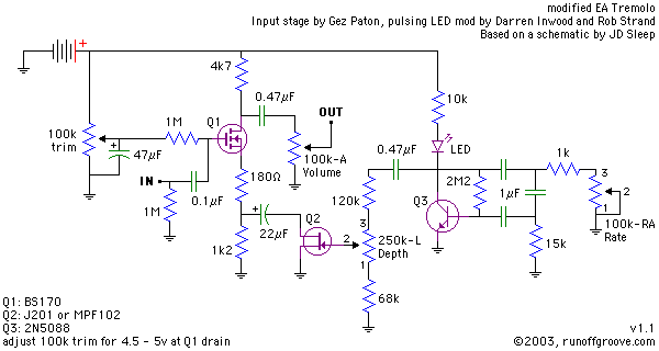
Let's say I wanted to use FETs like in the EA Tremolo instead of the LEDs.


When RG Keen did his Harmonic tremolo (see here: http://www.geofex.com/FX_images/FakeFenderVib3.pdf), it looks like he hooked up the source FETs to a 4.5V voltage reference and then fed them an out-of-phase signal.

The oscillation with the FET works by dropping the resistance when the voltage swings negative, and increasing its resistance when the voltage swings positive.

So here's the question(s):
If I hook up one FET's source to ground (as in the EA Tremolo) and the other FET's source to +9V instead of ground, and then feed them the output of the LFO that centers at 4.5V, will I get out-of-phase modulation of the two bands similar to what RG did in his harmonic tremolo? Or would I instead need to use P-channel devices? Or do I absolutely need to use out-of-phase LFO signals to get the devices to change their resistances counter to each other?

Although I could probably answer this myself on a breadboard, I'm feeling lazy ...