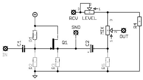
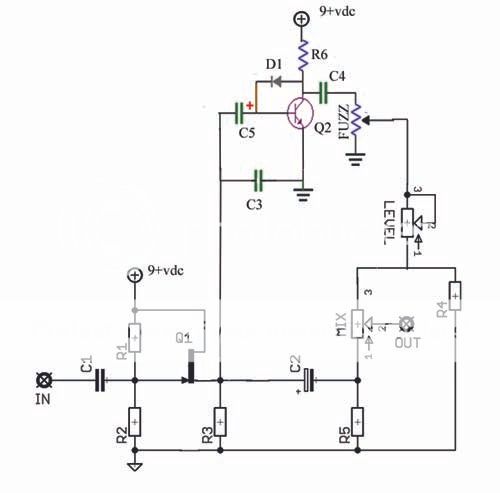
Hey Guys, I've got a question about the power supply section of a circuit. Here is the whole schematic:

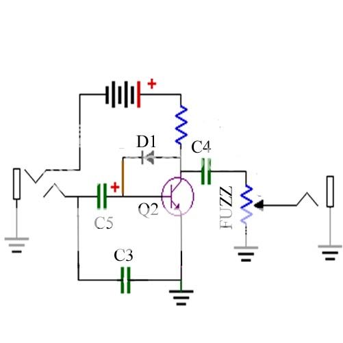
and the section in question:

I realize that this section is providing two different voltages. Is it also providing polarity protection? And if so, which components are doing that? I've seen it done with a diode before so I'm wondering.
Knowledge for knowledge's sake.
TIA
and the section in question:
I realize that this section is providing two different voltages. Is it also providing polarity protection? And if so, which components are doing that? I've seen it done with a diode before so I'm wondering.
Knowledge for knowledge's sake.
TIA