News:

Forum may be experiencing issues.

Main Menu
Menu

Show posts

This section allows you to view all posts made by this member. Note that you can only see posts made in areas you currently have access to.

Show posts Menu

Topics - midwayfair

#101
I've been busy!

Okay, so there aren't a ton of pedals to use these in, but if you have an amp with negative feedback, they're easy additions. But we do use negative feedback in things like Fuzz Faces (that's the 100K resistor), so maybe some of these will be of use!

Anyway, if you're not familiar with how negative feedback works, Uncle Doug has a good vid:


Here's a little schematic I drew with some ideas:


Note that a lot of these look familiar -- I'm just proposing putting them on the emitter or cathode of a circuit in a negative feedback loop, which makes it sort of "semi active", and won't load the transistor or valve it's affecting the sound of. (It will load the place you take the feedback from, but that's usually a low-impendance place in the circuit!), which could be extremely useful in some circumstances. They do remove some gain overall, but sometimes that's a good thing, and it's not as bad as some circuits. The mid scoop circuit I show, for instance, is a very mild notch, less severe than a blackface, but far GAINIER as well.
#102
Open Discussion / Bridge/Trem block suggestions
June 06, 2014, 09:36:52 PM
I think I broke the trem block on the DQcaster last night. It's still fine to play (it stays in tune, and it was practically decked to begin with), but no more wammy bar shenanigans for a while.

I was thinking instead of just replacing the block (which was steel by the way!), I might replace the whole assembly. I need something that can use the same holes if possible if I replace it. Is there anything else out there, or should I stick with just replacing the block?

EDIT: Okay, I'm an absolute idiot. I only broke the ARM.

Still ... anyone have suggestions for a better type of trem bridge that slots into a vintage spot without new holes?
#103
Traded Chris (CK1) for this over the weekend, and immediately set to work making a few improvements. :)


I'll be replacing the speaker grill with something that air can actually pass through as soon as possible. I want to get a new speaker, too.

Flip it around and it's got three knobs and only one input now ...


The paint scraped off pretty easily, allowing me to avoid an awkward moment where I don't know what the heck the knobs are doing.

And here's the revised guts as of right now:


I ditched/jumpered several resistors that do nothing but lower the gain of the circuit, increased the negative feedback to 10K, and then ripped out the tone control and revised the preamp stage to something pretty much like the woodchipper schematic I posted. The mids control is a variable cathode bypass cap (470nF), and the treble is a variant of the stupidly wonderful tone control, with a treble boost at ~1K being rolled in at the same time the treble cut is reduced.

It sounds really good right now (and it's crazy loud for such a tiny speaker). The tone controls are fairly mild overall, but it gets a little more glassy at the highest settings on the tone controls, and there's a good setting with all my guitars. The highest setting on the mids is much tighter breakup than it was with the 22uF.

I did several things to reduce noise, like put real tubes in (EHX 6v6 and a Tube Store matched 7025), repositioning some wires, shielding the heater and input wires (just wrapped in copper tape with a ground connection). Once I get a parts order in, I can increase the size of the filter caps, increase the resistance on the droppers, and hopefully kill the hum this amp is "known for" permanently.

Right now I have the cathode bypass cap still in on the second half of the 12AX7, but I might pull it out later.

No clips just yet. I plan on putting another recent gear purchase in front of it soon though ...


Which is a really awesome sounding mic. I gave the AT2020 to my friend and bandmate so that he could have a condenser, too.
#105


So pretty.
#106
The FCC recently lowered the acceptable frequency range of digital devices. Haven't heard about this? Don't worry, you're hardly alone. Even some of the biggest players out there haven't.

Effects Bay has a nice little write-up about a recent EHX dust-up:
http://www.effectsbay.com/2014/05/fc...ns-for-pedals/

The long and short of it is: anything with a digital clock that generates a frequency above 9,000Hz now must be tested for emissions. EHX got slammed with almost a half a million dollars in fines. Testing is expensive, and equipment to do so would cost thousands of dollars, putting it out of reach for I suspect, most small or even medium sized pedal builders. Shipping something used without a certificate could even potentially violate the FCC regulations, similar to trying to ship guitars internationally. I really hope that I'm being alarmist, but I'm going to have to check with my boss (work in a law office) to see if I'm misunderstanding anything.

What's this affect in your pedals, you ask?

Anything with a charge pump -- yup, all your Klones.

Anything that requires a clock chip to produce the effect -- analog octave down, bucket brigade delay/chorus/vibrato, etc.

PT2399 delays and other digital delays -- so far as I can tell, everything involved in making analog delay pedals, with one notable exception, is now in violation. That exception is tape delays. I'm sure we'll all be thrilled to go back to THAT technology.

Anything with tap tempo.

Every pedal you can think of based on the FV-1 -- this covers a LOT of reverb pedals.

All those reverbs based on the Belton brick -- this covers most of your other reverbs.

The list goes on. Why? Because digital audio circuits need to have clock frequencies well above at least 15KHz, preferably well above 20KHz, to get out of human hearing. So you're stuck either finding a testing method for your pedals (expensive) or lowering the clock frequencies into human hearing range (which would just be terrible).

More info here: http://www.diystompboxes.com/smfforum/index.php?topic=107145.msg972029
#107


Close-up of the board:


This is a fuzz made with all-glass components. Well, except for that power-filtering cap, but electros simply don't exist in glass that I've ever been able to find. :)

I've wanted to build this forever, but the resistors were almost impossible to get and are extremely expensive when the do pop up. Govt Lackey (Greg) was incredibly generous and hooked me up with enough to make a few pedals with -- most importantly with a few almost-impossible-to-find 500K resistors.

The capacitors are actually glass-encased SMD components that someone on BYOC posted about recently. This was really the final kicker, because it meant that I could do everything in glass instead of my original plan, which was to use metal caps (and probably metal transistors).

Since I had such a limited range of components, I had to design a new circuit. I'll post a small build thread with the demo in a moment, with the caveat that the project could probably use some refinement when using "real" components.

Oh, I forgot my note about the art, because I really liked it: I wanted a combination of faux 3D and two-dimensional cartoonishness for the ship itself. I thought it came out really well. I showed it to a friend who then asked if I could do something similar for his duo's EP cover! That was kind of neat.
#108
At a small club in Baltimore, the Windup Space, which is probably my favorite club here -- never too loud for the room and it always sounds great, and the owner/bartender is one of the nicest guys around. Maybe 75 people there, with chairs set up. And for extra cool, he had Cyro Baptista on percussion! The playing was awesome of course (his upright bass player in particular was just insane), like listening to a soundtrack while you make up the movie, and all done with just real instruments, loopers, and "a few" effects. Actually, far fewer effects than I imagined -- aside from the chaos pad on the "noise" parts, there was delay on maybe two songs, vibrato on one song, and fuzz or overdrive on about half, running through a ZT lunchbox amp.

I'm not sure I'd see him again -- I mean, there's only so much avant-garde stuff I can listen to -- but it was certainly a good experience and I'd recommend seeing them at least once in your life. :)
#109
Open Discussion / Wah shell opinions please :)
April 30, 2014, 01:34:14 PM
I'm slowly building up the parts for a wah ... I've got ye olde inductor and a Joe Gagan pot ready to go, and a WW2 in my Madbean cart.

Here's a rocker pedal I love the feel of: Ernie Ball VP.
Here's a rocker pedal I can live with but am not thrilled about: Vox.

How does the Smallbear or Pedal Parts Plus compare to the Vox?

Also: Hooker Lip Red textured, cookies and creme vein, or blue hammertone? ;)
#110
Open Discussion / RESPECT. Good Job, Cusack
April 29, 2014, 01:20:57 AM
http://cusackmusic.com/tiny-tap-delay/

My jealousy is boundless.
#111


Stage Fright, with a pretty cool little "Sweep" mod.

I was tinkering around with the trim pot, and trying to figure out what it was doing -- turns out it was adjusting the notch. And I thought, that's really interesting. But it really only had any action on the top half of the pot, and sounded best maxed out.

I was also fiddling with the FET, because I wasn't getting too much action on the 5-stage side. At first I figured I'd just swap it for a J201, because that sometimes offers a higher switching range (see the Shark Fin notes). It helped a little. But then I looked at the schematic, and noticed that the grounded gate meant it was really just acting as a diode. So I started plugging in some diodes, then realized that a higher Fv (up to a point) offered a far more extreme effect. I settled on a blue LED over a 3.3V or 4.7V zener because they didn't work without a blocking diode.

The I wondered -- what would happen if the sweep pot was bigger? Hooked up a 100K pot in series with the LED and got a nice big range. 500k was a little too much. 250K was perfect on the extremes, but bunched up a bit on the sides. A log taper fixed that and now the sweep gets "deeper" (moves toward bass) as the pot's turned up. For an even cooler effect, it also forms a CLR with the LED, so turning the pot makes the sweep AND the LED darker. The ability to tune the notch makes it an exceptionally versatile phaser now.

It was a bit of a pain while boxing. I had the LED sort of hard mounted to the switch, and then I could reach in with a small screwdriver and guide the LED to the bezel.

And for extra super added bonus thought ... if you move the sweep while playing, it sounds flanger-ish. No fooling. You could add a switched expression jack and use an Ernie Ball volume pedal as an expression pedal. Might be worth considering for anyone thinking of an add-on that uses the CV input. (I might build another one in the future and add an envelope control for the CV.)

I will definitely do a demo of this in my next batch.

That said, it wasn't the most pleasant build. There's really no option except top jacks to get this in a 125B, and the jacks leave almost no room for error if you want to use sockets for the LM13700s. Since I still haven't solved the problem of my soldering iron killing chips (I actually lost my first stage fright PCB due to that ... after I desoldered the chips, I couldn't get it to fire up, though I might revisit it with the possibility that the chips were bad), that meant I almost ended up with an effect I couldn't plug into.

I also had a near-disaster when I overtightened the toggle switch (trying to get the PCB as far from the jacks as possible) and broke it ... desoldering a 2PDT is NOT my idea of a good time. I also had to lower the board-mounted pots at the same time.

Finally, let me just say that I'm not really a fan of top mounted jacks when the design has the in, out, 9V, and ground connections at the bottom of the PCB! I don't mean to fault Brian for that part of the layout, as I'm sure things were exceptionally tight on this (and overall it was an easy board stuffing experience), but it just makes the wire running less than ideal. Especially because I don't think the in/out jacks will fit on the side except to do like Merlin and cut off the nubs of some plastic jacks to put them on either side of the switch.

Oh, and my last problem was that some of my LM13700s simply didn't work. They happened to be the set I was using in the first one I built -- not the desoldered ones, but from the same Tayda batch. Since I wasn't careful about separating my Tayda chips from my Mouser chips, I now have to dig through them to figure out if it's the builds or the chips in the OTA pedals that have been having problems. I just wanted to mention this if anyone else is having trouble getting theirs to fire or has a really weak effect ... though I did have one chip that didn't work at all, in a couple of them, it was simply one half of the chip that wasn't working. I found four that were in some stage of death. It could be a lack of ESD precautions (Tayda doesn't ship in protected bags), or just bad chips, I don't know.
#112
Build Reports / Duo Vibe and Grease Gun
April 20, 2014, 09:49:09 PM


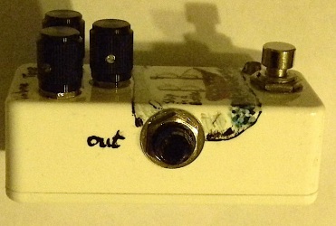
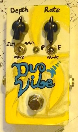
CJ's cool little vibe/phaser/filter effect. I modified it to have a rate LED, and made some adjustments to use a super bright LED (though in the end I probably would have been fine with the regular red LED). I also used an on/off/on switch for the mode, so it has a mode that's just the two wobbletrons in a row.

Sounds pretty cool. The "big cap" mode, which I labeled filter, is very unusual, sort of a cross between a filter and phaser effect, and I think the project is worth a build just for that mode.

Literally the only thing I would have considered changing about this is to change the output buffer to a gain stage and have an output trimmer or volume control. On lower depth settings, I have a very small volume drop, though it's at unity otherwise.

I wasn't sold on the knobs, but cream was just wrong, the enclosure wasn't "white enough" to use refrigerator white, and chrome didn't look right.


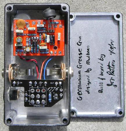
Brian's Grease Gun, with a germanium transistor and a pair of OA126 diodes.

When I moved it from the breadboard to the PCB, I made some changes to the coupling caps -- the output cap was overkill, and there seemed to be something wrong with the decoupling cap after Q1 -- it was 2n2 in the original, but there was only a very tiny bit of signal coming out of there, even though the calculator says that it should pass most of a guitar. I ended up just using 100nF for every coupling cap in the circuit and it's a very dirty boy now.

Finally, in addition to the germanium transistor in Q2, I also decided to just use a BC549C in Q1 because the input impedance was bellow 500K, so there was no benefit IMO to using the (more expensive) MOSFET. Incidentally, the joke on the enclosure about magical germanium is a nod to there being almost no difference in sound here between the BC549C and the germanium in Q2 and that the OA126 diodes have the same Fv (and thus sound basically the same) as the 1N914s called for. ;)

I'd recommend this one with the caveat that you should be prepared to try a couple different values in place of that 2n2, and to think of the pedal as more as a roleplayer.

What's it sound like? Kinda greasy. No, really. The treble cut on the tone knob is fairly deep, and the feedback diodes are a little spongy sounding, and it also gets pretty dark on lower gain settings. It sounds really cool pushing the yellow channel on my Hot Rod Deluxe, and it also sounds pretty neat stacked after something else into the rhythm (blackface) channel on my Imperial. I know Brian plays an AC30, so I suspect that the tone knob's extremeness is very friendly with a cranked vox.
#113
This happens once in a while, and I have no satisfactory explanation for it: You turn down the guitar pot and you get a bunch of hum. Put it at full and everything's fine and dandy.

In this case, it's the grease gun I just built, though I think I've had it happen in at least one pedal before. I know other people have posted about it, and I've never seen a good explanation.

My Grease Gun might not be too useful for troubleshooting (basically I've made a bunch of subs -- like all my coupling caps are 100nF now, so it's going to be hard to just say what the main problem is), but what might be useful is knowing what I've done to try to get rid of it:

1) Input series resistance? -- I see this floated as a solution sometimes. Nope.
2) Change bias resistors? -- No meaningful effect.
3) Cut the bass? -- To some extent this works (it's low frequency hum after all), but then I lose a bunch of distortion and signal!
4) Change the input device? -- No difference in my case with a BJT, MOSFET, or FET (with the positive bias removed) in Q1. Hum persists.
5) Buffer the input? -- I was certain this would do it -- after all, the problem only manifests when the guitar pot is turned down, so if the guitar pot is decoupled from the circuit, then it must ... Nope!
6) Move some wires around -- no change (so it's not RF, but I knew that)
7) Remove the pulldown? -- Nope.
8) Extra power filtering/100R on the voltage input? -- No change.

I am just mystified. I mean, I'll live with it, but I wish I knew what caused it. There's nothing about Q1 that I haven't built before without issue, and it's basically half a big muff, which despite overall thermal noise being an issue doesn't exhibit the volume pot issue I've got here.

So this is more of a general troubleshooting thread I guess.
#114
Build Reports / Something's FSHy!
April 13, 2014, 02:17:31 AM
I has an FSH! :D


I've wanted this effect for a very long time. Brian's board and build notes made it easy. It fired up the first time, but as you can see, there are some extra things going on:

First, I had quite a bit of noise from one of the 3080s. So I made myself a little daughter board to use an LM13700 instead, and this really improved the signal to noise ratio.

Buffered bypass! The little piece of perf is just the two "output" caps, a 1uF for buffered, and 220nF for the main circuit (it's a tiny bit higher than stock, but it doesn't really matter because it passes all frequencies anyway).

I jumpered the 10K at the input to avoid signal loss in bypass, and reduced R4 (to 47K) to get a little above unity (it was just slightly below).

Finally, I lowered the threshold by reducing R15 to 10K, so that it works better with single coils, especially my tele.

I'm super thrilled with the art. No idea where the idea came from, but it made me giggle, so there it is.
#115
I have a few PCBs that just won't get built and I feel bad holding onto them.

There are 4 PCBs here, each with their own unique requirement.

1) JMK Scuba Muff -- I dearly wanted to build this, but the fact is it's sized for a 125B and I just never keep them around the house. It's a super awesome muff variant (I breadboarded it) that can get a ton of sounds, almost as many as a Pharoah.

To get this one, you must agree to film or record a demo of the pedal in action.

2) JMK Delay -- this is Jacob's standard delay. You can build a Rebote or DBD on it, for instance.

To get this one, you must agree to post a build report of the finished delay.

3) Bacon Bits -- this is the older version, without the warm switch. This is a beginner-friendly build. To get this, you must have fewer than 100 posts here, or have started building within the last 6 months.

4) Whisker Biscuit -- CJ's layout of what is, quite honestly, my favorite "big muff" variant. I have two of these to give away. To get this, you must answer the following question: What is the brightest object that currently exists in the known universe? I will accept more than one answer for this, with one board for each correct answer.

5) Neptune Delay -- this is a black PCB, and I'm not sure which run it's from. Another CJ PCB (I have a few ...). To get this, answer me this: If I take away one of Neptune's points, what is he holding.

Have fun!
#116
I've got some hum appearing at pin 2 of IC3. It gets quieter when the envelope is "open," and gradually comes back in as the envelope settles; it's also a little louder as the

It's perhaps 1/3 as loud as the guitar signal, so ... kind of obnoxious. I'm not sure if it's just the CA3080s or what; I expect them to be noisy.

It also gets quieter when I move my input guitar cable or reposition the pedal. That's weird. :/

The circuit works just as it should otherwise.

Anyone think a daughter board for a 13700 conversion would be quieter?
#117
A couple customer builds.

Cardinal with all four pots external and one of the tiny 2P4T switches to do all four modes -- those switches are the same size as a potentiometer, so it was pretty easy to fit. I just bent the pins down. Works great because you only really need one side of the switch, so if you wanted to get really fancy and change something else, the other pole could probably have been used. I could probably use them in a 1590A build, even, as they're about the same height as a pot with a dust cover once I put 3M tape on them.

Other things: This has my current biasing preference (6V on all FETs, rather than the attenuated Q1) and 2N5457s in all three, and the customer uses british style amps, so I just removed the bypass cap on Q2. Using real FETs makes a big difference in the gain structure ... still kicking myself over those Tayda FETs.


And another Blue Warbler version 2 -- this has my final preference for the depth pot from the build document, and the super slow speed pot (100K), which sounds SUPER smooth at the lowest setting. Maybe someday I'll get to build myself one. I don't have any in the house anymore, not even my version ones. :P

#118
3 x 3

Only 125B template I could find was only two pots.

Could also use a 3 pot and extrapolate, but I'd rather not.
#119
I keep seeing a bunch of projects with +18V on an op amp. Come on, guys, live a little. Split rail! It's fewer parts. It MORE headroom by at least a volt. It is every bit as easy. Plus you can do doublers on both rails and blow up some chips! Okay, let's not do the last one. :D

Discrete component circuits with charge pumps get a pass, because no one likes putting a trimpot on both the drain and source of a FET.*  :P

That's my rant for the day. Pies may be directed at my face. No rotten vegetables, please.

*But in all seriousness, I guess I could have done split rail with the Hamlet.
#120
First, I am by no means saying that there's anything wrong with the workalikes. I buy them all the time and have used them in several projects and almost every time they work great.

The LDR side in the 5C1 and 5C3 clones, by every metric I've been able to measure them, is basically identical.

I HAVE, however, noticed a kind of weird difference. It's in the LED side. Essentially, the LED in the Macron clones works just like a normal superbright LED. The forward voltage is pretty much spot on to a white LED, and it seems to draw the same amount of current.

The VTL5C1s have the biggest noticeable difference. They seem to require less current limiting to get to their brightest point. The measured forward voltage is ... higher than a green LED but lower than a blue LED, at least on the few I have left here. (I used to have dozens, but I used them all!) I got just under a 3V drop on mine.

The result is that under some circumstances, when the ON resistance is critical, just dropping in the Macron to replace the Vactec part might require an adjustment. In the circuit I was messing around with, I got a lower on resistance with the macron but higher dark resistance with the vactec under the same conditions. Extremely similar after testing three of each (so they're also very consistent).

I'm not too keen on cutting open a few $8 parts to see what's inside, but I wonder if anyone has any insight into this, or if anyone's observed something similar.

I'll be xposting this, so if I hear anything else where I'll let people know.