
Super clear and succinct – understanding it now, thank you!
- Welcome to madbeanpedals::forum.
This section allows you to view all posts made by this member. Note that you can only see posts made in areas you currently have access to.
#1
General Questions / Re: Rat with Dual Opamp – mind helping with the last section?
September 13, 2023, 02:05:41 AM #2
General Questions / Rat with Dual Opamp – mind helping with the last section?
September 12, 2023, 03:59:44 AM
Hello!
I'm mucking around with a circuit and would love some knowledge dropped on me.
I'm wanting to make a Dual Opamp Rat but the second stage is bugging me.
Here are my questions:
– Original Rat inverts the signal – is there a reason I shouldn't keep both IC's in a non-inverting state? I'm wanting to eventually wrap a clean blend around it so I assume I should keep both IC's the same
– Will I have enough output to just run the second ic as a buffer?
– If I don't, and want to add some gain, I'm getting confused when to send something to VR vs when to send something to ground.
– I'm also a bit confused as to when to add a VR reference at the input of the IC – some circuits use it (like a HoneyBee), and others don't (like a Timmy)
Here's my schematic
#3
Tech Help - Projects Page / Re: Green Bean problems, fried resistor
July 06, 2016, 02:05:22 AM
Pictures of the other side of the board could help too
#4
Tech Help - Projects Page / Re: Green Bean problems, fried resistor
July 05, 2016, 01:17:27 AM
Sounds like dumbness but considering that R18 is pretty much right at the input of the dc power, I'd be first looking at the power you're using.
Is it 9v DC? Check it's not AC or way higher than 9v.
Is there any way you can check it using a battery?
Have you tried changing out those parts you mentioned?
I think if c11 was going straight to ground it wouldn't necessarily get the resistor burning out.
Is it 9v DC? Check it's not AC or way higher than 9v.
Is there any way you can check it using a battery?
Have you tried changing out those parts you mentioned?
I think if c11 was going straight to ground it wouldn't necessarily get the resistor burning out.
#5
How Do I? Beginner's Paradise. / Re: Etched vs Fab PCB
June 30, 2016, 09:42:31 PM
They're not stupid questions at all! Better to ask and get going quicker IMO
Yes, you put the component on the blank side and solder the legs to the copper.
Yes, on a dual layer silk screened PCB you match up the diagram with the component and solder to the non silk-screened side. This will work 95% of the time - things to watch out for are IC's and transistors as sometimes you need to check the right pins are going to the right places - this is why you'll often get recommended to use little sockets. It makes for an easy fix if you get it wrong and allows experimentation.
Yes, generally you'll solder pcb mount pots and switches on the dual layer pcb silk side so they'll face towards the front of the enclosure, the other components will face the back.
Soldering non-pcb pots and switches with wire comes down to preference really but I personally prefer soldering them to the silk side on a dual layer pcb.
#6
Open Discussion / Re: Active filters – how does this one work?
January 28, 2016, 11:34:27 AMQuote from: samhay on January 28, 2016, 10:49:01 AM
I am working from the assumption that the 2nd op-amp doesn't have it's input drawn the wrong way round, as it would be an oscillator if that were the case.
The tone control works against C7 - which could be connected to ground rather than VR - to give you a low pass filter with corner frequency from:
470R vs 22n = 15 kHz down to (470R + 10k) vs 22n = 690 Hz.
The tone control will not have much effect on the second op-amp, which is an inverting low-pass shelving* filter with a corner frequency of ~300 Hz.
That's why it sounds dark. If you decrease the 1.5n cap to somewhere in the 100-470p range, it should sound like a guitar effect. The 10p is just there for good behaviour.
*Shelving in that at low frequency you have a gain of -6.6(ish) and at high(er) frequencies you have a gain of -3.3(ish).
The peak gain of about 6.6 might be enough to clip the rails. If it sounds fizzy, I would increase R7 to 220k or 330k.
Ha, whoops. My mistake - I got caught out by an earlier schematic that that issue, I thought it was this one.
This is awesome, thank you so much for that...and being gentle on my noobness!
#7
Open Discussion / Active filters – how does this one work?
January 28, 2016, 10:11:43 AM
I'm tinkering with a Blues Pro overdrive I have laying around and I really need to get a bit more treble/top end presence out of the tone control.
He's used an interesting high pass filter on the second part of the op amp and I'm wondering if anyone can explain a) how this works and b) how do I tweak it to get more top end out of it?
In particular the two resistors and caps together are throwing me a bit - I would understand a bit more if it was as simple as a cap in parallel with a resistor in the ic loop but I'm not sure what the combination does?
Here's a schem (note that the second opamp has its + and - round the wrong way)
#8
Open Discussion / Re: How are you guys storing/organising your stuff?
January 27, 2016, 10:33:24 PM
Damn, I'm totally putting a box around my drill press when I get home tonight.
#9
Open Discussion / Re: How are you guys storing/organising your stuff?
January 27, 2016, 07:53:29 PMQuote from: Jabulani Jonny on January 26, 2016, 02:48:11 AM
I use small 2.5x3 inch clear bags. These: http://www.amazon.com/gp/product/B003ZZYAIA?psc=1&redirect=true&ref_=oh_aui_detailpage_o07_s00
and 9 pocket/page baseball card holders. This: http://www.amazon.com/gp/product/B00LPURVRE?psc=1&redirect=true&ref_=oh_aui_detailpage_o08_s00
I label everything with a sharpie and it makes it super easy to store a bunch of stuff in a single three ring binder. I have a section for resistors, in order of course, caps, trannies, leds, diodes, etc.
For trannies and anything sensitive to static, I just trim down the little static bags from Smallbear or Mouser and slide those into the baggie as well.
This system works really well for me and helps me keep my stock in order. Speaking of keeping stock, attached is a spreadsheet I use for keeping up with ordering for projects. I have a list of all the parts going down the left, usually with source and part name (although may be dated now), then I put a column for the project and fill in the needed parts. The column on the far right calculates what I need based on my current inventory. Admittedly you have to update that column's formula if you insert a bunch of project columns, but it's not too bad.
Hope someone can find some use out of it!


I use the ringbinder/pocket system myself and I think it's amazing. It's super compact and easily navigable. I have a folder for caps and resistors, but I'm storing everything else in compartments.
I think we're on the same wavelength, thanks for the spreadsheet!
#10
Open Discussion / Re: How are you guys storing/organising your stuff?
January 24, 2016, 10:12:40 AM
Ha! Exactly my feels.
I'm trying to figure out how to get a system that is easily accessible but also easily reconfigurable, and by that I mean if I get a 422k resistor, I want it to be easy to shuffle space around if I need to make room for a random value.
Also wondering if some sort of inventory system would be worthwhile or just cumbersome.
For the moment, I have all the resistors and capacitors contained in ascending order in two arch files with basketball card inserts, so there's a pocket and a little plastic bag for each value and that seems to be working reasonably well but parts like LEDs, transistors, diodes, and pots are just all over the place in a fabulously frustrating explosion of hardware.
#11
Open Discussion / How are you guys storing/organising your stuff?
January 24, 2016, 08:18:21 AM
Just wondering how you lot are categorising/storing your parts?
#12
Global Annoucements / Re: Important: Read This, Please
January 20, 2016, 01:37:16 AM
Yeah, I saw the error message up there, hoped you had some backups.
What a bunch of dicks not getting on to it pronto.
What a bunch of dicks not getting on to it pronto.
#13
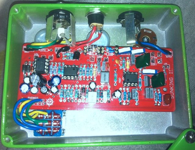
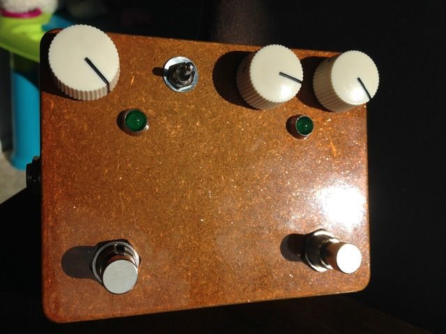
Build Reports / SunLion & Sunking II
May 17, 2015, 02:25:21 AM
First, the Sunking. I didn't realise how little margin for error drilling a 1590BB has for the Sunking II but we managed to get it in there with a little light remedial work.
Had an issue where the 422k and 392k resistors weren't working but one that got sorted, we were away. What a great sounding circuit! I put little slider switchers on the board so I could set and forget.

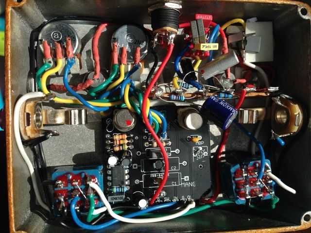
Second, the Sunlion. This ended up being a total mission to fit all the stuff in due to having a pre-drilled case that didn't put the jacks low enough. I had to remove the nice PCB mounted pots and wire them in. I had a Madbean Rangemaster board but I decided to go against using it as the new version a) wouldn't fit, b) used a BS250 that I can't source anywhere, and c) I already had the charge pump on the Mangler PCB. I used a three way on-off-on switch for the Rangemaster input and used a terminal strip layout as devised by RG Keen. It's all a whole lot less tidier that I'd like; it's a bit of a spaghetti junction but it works and it sounds good so all's well.
Had an issue where the 422k and 392k resistors weren't working but one that got sorted, we were away. What a great sounding circuit! I put little slider switchers on the board so I could set and forget.
Second, the Sunlion. This ended up being a total mission to fit all the stuff in due to having a pre-drilled case that didn't put the jacks low enough. I had to remove the nice PCB mounted pots and wire them in. I had a Madbean Rangemaster board but I decided to go against using it as the new version a) wouldn't fit, b) used a BS250 that I can't source anywhere, and c) I already had the charge pump on the Mangler PCB. I used a three way on-off-on switch for the Rangemaster input and used a terminal strip layout as devised by RG Keen. It's all a whole lot less tidier that I'd like; it's a bit of a spaghetti junction but it works and it sounds good so all's well.
#14
Tech Help - Projects Page / Re: Sunking II gain problems
May 15, 2015, 05:02:54 AM
Thanks all, I feel very welcome here 
Me also. Cheers for these projects; my ears are ringing like crazy after boxing this guy up!
Quote from: madbean on May 15, 2015, 12:30:49 AM
Interesting. Well, glad it all worked out.
Me also. Cheers for these projects; my ears are ringing like crazy after boxing this guy up!
#15
Tech Help - Projects Page / Re: Sunking II gain problems
May 14, 2015, 11:48:00 PM
Ok, so I replaced the whole power section with no change BUT happily found the issue.
I'd tried to jimmy up some 422k and 392k resistors through putting some resistors in parallel and series jiggery pokery, and as soon as I removed then and just replaced them with 430k and 390k resistors it all magically worked.
Hooray!
I'd tried to jimmy up some 422k and 392k resistors through putting some resistors in parallel and series jiggery pokery, and as soon as I removed then and just replaced them with 430k and 390k resistors it all magically worked.
Hooray!