
Looks fantastic! Kind of tempted to order a board and give this one a go.
- Welcome to madbeanpedals::forum.
This section allows you to view all posts made by this member. Note that you can only see posts made in areas you currently have access to.
#1
Build Reports / Re: Current Lover/Deluxe Electric Mistress alike build
January 20, 2012, 09:24:10 AM #2
Tech Help - Projects Page / Re: Dirtbag BBD bypass
January 16, 2012, 06:59:09 AM
Apart from fake (relabelled MN3008) BBD chips, the only other thing that I can think of that would give half the delay time is either C41 (240pF) or the delay pot being half of their specified values. Check that you didn't accidentally swap C31 (120pF) with C41 (240pF).
#3
Tech Help - Projects Page / Re: BIASing Dirtbag Deluxe
January 10, 2012, 09:56:23 AM
I'd say that's normal since the signal has only gone through half of the delay stages.
#4
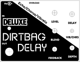
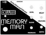
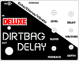
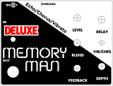
Build Reports / Re: DirtBag Deluxe build
January 10, 2012, 09:45:38 AM
Here's several different versions of the decal (click for full-size versions). I've made a couple with a 'Dirtbag' text instead of the 'Memory Man'. The images are 600DPI so if you print at 100% scaling it should all come out correct (highly recommended to do a test print first!) On Windows I recommend using Irfanview to print out to the correct size (there's an option to use the image resolution in Irfanview's Print dialog), or on Mac OS X just change the scaling to 100% on the print dialog.


#5
General Questions / Re: Dirtbag pot layout for PPP drill instructions
January 08, 2012, 03:48:48 AM
Here's mine - the pots are about 5mm closer to the top of the enclosure, but that's probably not a big deal. I just went as close as I could to the wall of the enclosure to save as much space as I could.
I don't think the positions of the holes are submillimeter-critical, especially if you solder the pots after drilling the holes. When you place the pots in the PCB pads, there's a bit of play before soldering. I drilled my holes at 7mm (pretty much the same as 9/32") and this gives a bit more room to move as well.
I think your dimensions look OK to me - I guess you could always drill the holes in a piece of plastic or wood and test-fit everything before soldering the pots and switch.
Edit: I completely overlooked the fact there's a drilling template in the build doc, and this has a larger gap between the PCB and the top of the enclosure. I guess this is needed if you're mounting the DC jack at the top to give some clearance. I'll shut up now (where's the embarassed smiley icon...)
#6
General Questions / Re: Dirtbag pot layout for PPP drill instructions
January 08, 2012, 02:58:53 AM
I used these pots: http://www.smallbearelec.com/Detail.bok?no=692
For these pots, the offset of the terminals from the center of the pot is 16.5mm.
My drilling layout dimensions differ from yours, the biggest difference is the offset of the pot holes from the top of the pedal (mine is much less than yours) - I'll post a picture & dimensions of my layout in a little bit.
#7
Build Reports / Re: DirtBag Deluxe build
January 08, 2012, 12:00:02 AM
You're right, I guess strictly speaking the label should be 'Vibrato / Chorus' to match the switch positions.
#8
Requests / Re: More compression?
January 02, 2012, 01:05:02 AM
Just wanted to mention that I finished and confirmed the schematic for the Pigtronix Philosopher's Tone a little while ago over at FSB, and the results are in that link to the FSB thread posted earlier. Harald from Sabrotone made an awesome vero layout (with onboard pots no less!) - I built this vero and confirmed it working.
IMO the critical component on this circuit is the LDR/LED that controls the automatic gain adjustment. I tried a couple of different LDR's I had laying around with difference characteristics, and found they didn't provide a quick enough reponse for a sudden hot signal, or didn't give enough gain for quiet signals. The VTL5C6 as in the original pedal works fine though, so keep this in mind if you build it. I don't know what LDRs would be suitable as a substitute, you'd have to look at the spec sheet for the VTL5C6 and compare to the LDRs.
IMO the critical component on this circuit is the LDR/LED that controls the automatic gain adjustment. I tried a couple of different LDR's I had laying around with difference characteristics, and found they didn't provide a quick enough reponse for a sudden hot signal, or didn't give enough gain for quiet signals. The VTL5C6 as in the original pedal works fine though, so keep this in mind if you build it. I don't know what LDRs would be suitable as a substitute, you'd have to look at the spec sheet for the VTL5C6 and compare to the LDRs.
#9
Open Discussion / Re: Pulsar Pro --- Decal Pro FX issues >
January 01, 2012, 06:38:54 AM Wow ... that looks fantastic! I'm impressed by how good that looks, and definitely inspired to try this out. I guess the main problem being where I am might be finding a supplier for the KK-2000 adhesive.
#10
Build Reports / Re: Dirtbag Deluxe
December 29, 2011, 12:46:31 AM
I use a stopwatch - set the delay time knob to max, add in some repeats so the delays hang around for a couple of seconds. Hit a staccato note on the guitar and the 'Start' button on the stopwatch simultaneously, and press the 'Lap' button on the stopwatch for very echo. I just take the average of a few readings.
If you don't have a stopwatch there's plenty of free stopwatch-type apps or online tools out there for your phone or computer.
If you don't have a stopwatch there's plenty of free stopwatch-type apps or online tools out there for your phone or computer.
#11
Build Reports / Re: Current Lover (Deluxe Electric Mistress)
December 24, 2011, 01:31:57 AM
Good stuff! Looks great. I've got my shopping list almost compiled to tackle this one, and a couple of other pedals.
#12
Build Reports / Re: Simply a Sea Urchin
December 22, 2011, 06:09:30 AMQuote from: eldanko on December 22, 2011, 03:59:41 AM
REALLY elegant bro! Well done!
Elegant is the exact word I though of too! Super classy stuff, love it.
#13
Tech Help - Projects Page / Re: Dirt Bag V3205 Question
December 20, 2011, 03:09:59 AM
Barring a build fault (solder bridges etc) or component failure, it might be a biasing adjustment issue. There's a relatively narrow range of adjustment of the bias trimmers, outside of which there will be no signal passed through. If you have an oscilloscope or audio probe this is fairly straight-forward to adjust for each chip (apply a signal to the input and probe the output of pin 3 for each chip while adjusting the corresponding bias trimmer for minimal distortion). The build doc has a good method for calibration.
Also check your ICs' orientation, and perhaps measure and post your (DC) voltages for each pin of each of the ICs.
Also check your ICs' orientation, and perhaps measure and post your (DC) voltages for each pin of each of the ICs.
#14
Build Reports / Re: Yellow Shark - First Etched Enclosure
December 19, 2011, 07:23:11 AM
Gorgeous! That's such a nice finish. It's been ages since I etched an enclosure, I just may have to get back into it after seeing this.
#15
Build Reports / Re: DirtBag Deluxe build
December 14, 2011, 11:00:08 PM
Here's the PCB transfer image for the IO board. I used PCB-mount Cliff-style jacks. You could use regular PCB mount jacks that have the thread bit sticking out, but then you won't really be able to remove the board from the enclosure without desoldering the jacks.
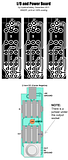
The image is quite large, it's 600DPI so print at 100% scaling and it should come out correct. I recommend using IrfanView on Windows to print this out, since the Windows default image viewer doesn't seem to print at the correct size (at least for me, that is).

The image is quite large, it's 600DPI so print at 100% scaling and it should come out correct. I recommend using IrfanView on Windows to print this out, since the Windows default image viewer doesn't seem to print at the correct size (at least for me, that is).